Troubleshooting
6-15
Part 1124631_01
E 2015 Nordson Corporation
Problem Controller Board Corrective Action
2. Controller Board Fails to
Start Up
a
b
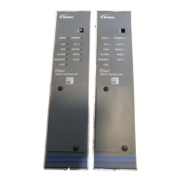
Note the following components
on the Controller Board:
a. DS14
b. DS15
The control switch on the front of
the pattern controller switches
power from the 24 VDC Power
Supply to the Controller Board
and the LCD touch screen. Refer
to the System Schematic in
Specifications, Section 7.
Power to the Controller Board
canbeobservedbyDS14inthe
upper right corner of the board
(item a).
Power for the CPU (processor) is
derived from the 24VDC with an
on-board regulator on the
Controller Board. CPU
Power is indicated by DS15 (b).
FortheControllerBoardtorun,
both CPU power and
24 VDC power LEDs must be lit.
Confirm Power to Touch Screen
a
b
c
d
e
Note the following components
on the Controller Board:
a. JP8
b. JP7
c. Com
d. 24 VDC
e. F1
Power to the touch screen can be
confirmed by the screen being lit.
S Check for 24 VDC input
power at JP7 between pins 1
and3asshowninthefigure
on the left.
S If 24 VDC is present, check
fuse F1 for continuity and
replace if necessary.
S If 24VDC is not present,
check the output voltage of
the Power Supply as shown in
the figure on the left.
Continued...

 Loading...