Installation
3-7
Part 1124631_01
E 2015 Nordson Corporation
Internal Wiring
Allow only personnel with appropriate training and
experience to operate or service the equipment. The
use of untrained or inexperienced personnel to
operate or service the equipment can result in injury,
including death, to themselves and others, and
damage to the equipment.
Warning:
Warning:
Equipment must be properly grounded and fused according to its rated current consumption ( see ID plate).
Failure to follow the safety procedures can result in serious injury.
JP2
JP3/4
JP4
JP17, JP18,
JP5
JP16
Install cooling fan if needed
(optional)
*Install PG connectors from
ship-with kit as needed
AC Input
PE (Ground)
Conduit
Trigger (1-4)
Encoder (1)
Run-up Out (1, 2)/
Machine Stop
Outputs
Applicator Outputs
(4)
System
Input/Output
(4 In, 2 Out)*
Connecting
Location
8
9
4
(External 24 VDC)
4
3
L2
L1
L2
/N
PE/G
/
RUN UP #1
OUTPUT
RUN UP #2
OUTPUT
Quadrature
Encoder use
1, 2, 3, 4, 6, 7, 8
Single Phase
Encoder use
5, 6, 7, 8
Ref
JP19
*
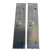
Figure 3-8 Internal board and cable connection details

 Loading...