Overview
2-7
Part 1124631_01
E 2015 Nordson Corporation
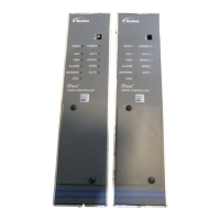
See Figure 2-4 for the location of the f ollowing components.
Base Panel Component Functionality
2. Trigger (1 – 4)
S Connects up to four (4) assignable
triggers.
S Assigns trigger to any applicator.
S Assigns a single trigger to multiple
applicators.
S Trigger masking prevents false
triggers.
S Measures and displays product
lengthon-screeninreal-time.
S PNP/NPN type trigger inputs are
compatible with all legacy and
industry standard photo-eyes.
3. Encoder
S Supports one encoder
S The following types of encoders can
be used:
S quadrature encoders (RS422)
S single phase encoders (NPN)
4. Run-up Outputs and/or
Fault Machine Stop
One or two run-up outputs, each
connects to a 0-10 V and 4-20 mA
pressure transducer.
Connects to a PLC input or machine
stop circuit (N.O and N.C. contacts).
5. Applicator Outputs (1 – 4)
S Supports four pattern channel
outputs
S Outputs a re 24 VDC, 1Amp
maximum per channel
S Multiple solenoid coils can be used
on one channel up to current limit
S Using an optional external power
supply the system can support up to
2Amp maximum per applicator, up
to a total of 6 Amps.
6. AC Input Input voltage:120/240 VAC
7. Fan location This is optional. A cooling fan can be
installed in this location.

 Loading...