2-46
Equipment
AN2016 Cabinet User Guide Rel 1.0 Standard May 1999
Configurations of the DSX-1 #2 includes one of the following:
• DDM+ shelf
• Soneplex loop extender shelf
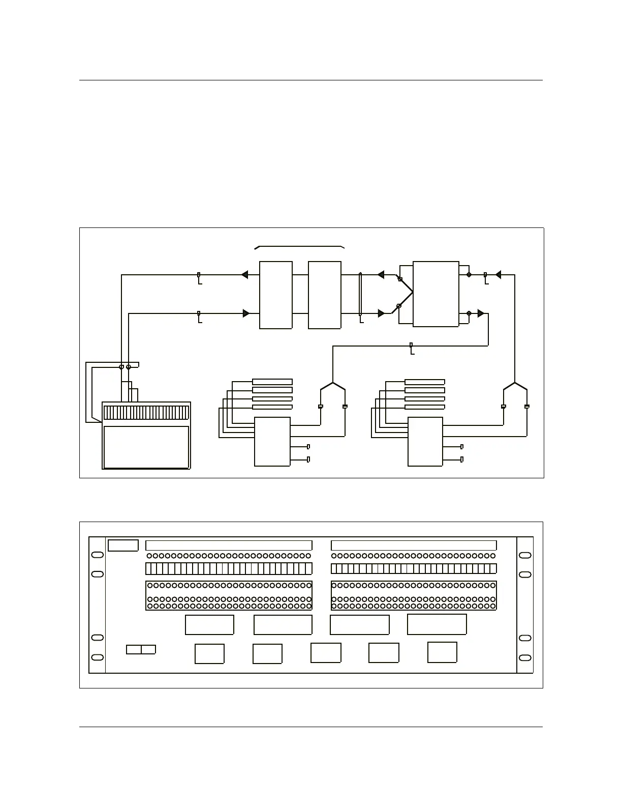
In a configuration providing the DDM+ shelf the ABM #1 shelf is
interconnected with the DDM+ shelf through the cross-connect DSX-1 #2 (see
Figure 2-34 and Figure 2-35).
Figure 2-34
DS1 wiring diagram DDM+ and ABM #1 shelf
AN0095.eps
Figure 2-35
DSX-1 #2 layout for DDM+ and ABM #1 shelf
AN0098.eps
CEP
CEP
DS1 IN
DS1OUT
ABM 1
30 32 34 36 38 40 42 44 46 48 50 52 55
DSX-1 2BDSX-1 2A
DS1
IN
DS
1
OUT
P1
P2
P1 P2
IN
1-2 8
OUT
1-2 8
INN
1-2 8
OUTN
1-2 8
OUTN
1-2 8
INN
1-2 8
OUT
1-2 8
IN
1-2 8
DSX-1 2
NTNR80BA
DS1 PB: NT4K31 AA
DS1 IN: NT4K32 AA
DS1 OUT: NT4 K33 AA
DS1SPC
TX(OUT)
1-100
DS1 TX (1-25 )
DS1 TX (26-2 8)
DS1SPC
RX(IN)
1-100
DS1 RX( 1-2 5)
DS1 RX( 26 -28 )
DDM-PLUS
N/C
N/C
N/C
N/C
1-25
26 -50
P1
P2
1-2 5
26 -50
P1
P2
NTNR81BA
NTNR81AA
J0 2A,J0 2B, J0 2C,J0 2D
J0 2E,J0 2F ,J02 G
J0 3A,J0 3B, J0 3C,J0 3D
J0 3E,J0 3F ,J03 G
J0 1A,J0 1B, J0 1C,J0 1D
J0 1E,J0 1F ,J01 G
FRAME GRD
FRAME GRD FRAME GRD
FRAME GRD FRAME GRD
51 -75
76 -100
51 -75
76 -100
*29-100
NOT USED
*29-100
NOT USED
NTNR80BA
NTNR81CA
DS1 PB
DS1 PB
GND
-48V
TL
MON
OUT
IN
TL
MON
OUT
IN
A
C
K
T
S
B
C
K
T
S
ABM 1 SHELF
DDM-PLUS EXTENSION SHELF
DSX-1 2
1 2 3 4 5 6 7 8 9 10111213141516 1718192021 23 24252622 27 28
1 2 3 4 5 6 7 8 9 10111213141516 1718192021 23 24252622 27 28