Equipment
2-23
User Guide Rel 1.0 Standard May 1999
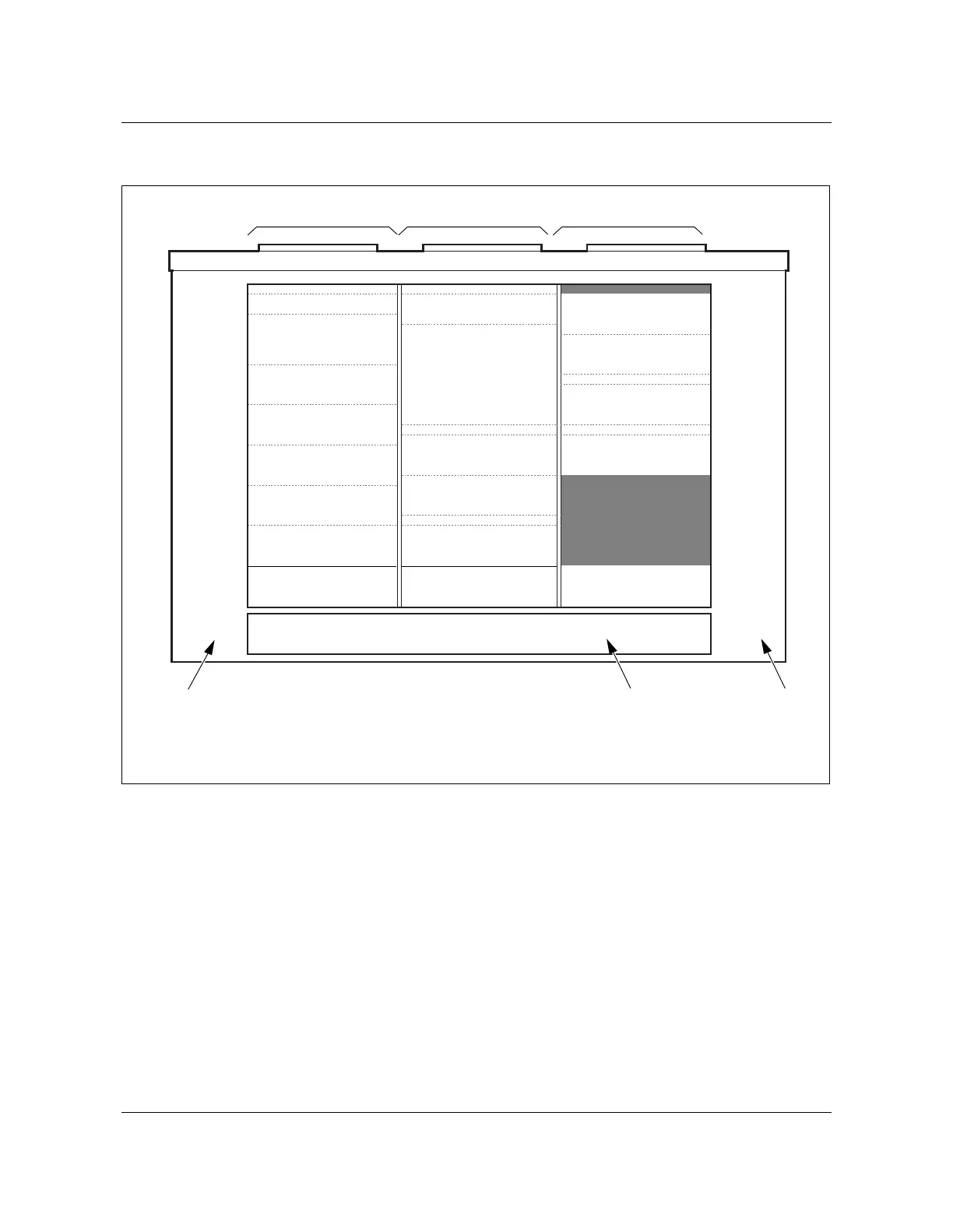
Figure 2-14
672-line configuration (rear view)
AN0058.eps
864-line AccessNode system
This configuration consists of 864-line AccessNode system. Two ABM
shelves are required to support the system capacity. The AccessNode system
is equipped with 9 copper-distribution shelves that provide up to 96 lines each.
The extended system configuration is equipped with a DSX-1 cross connect
shelf to feed DS-1 lines from the primary ABM shelf to the second ABM shelf.
The 1–864 VF lines are routed from the system out to the surge protection
center (SPC). You can splice the VF lines directly into the outside plant (OSP)
cables.
See Figure 2-15 and Figure 2-16 for a view of the equipment frame/bay layout.
Heat exchanger
plenum ECU
LCAP
BIP
ABM 1
Fan shelf
CDS 1 (1)
CDS 2 (1)
Shelf spacer
CDS 3 (1)
RMU
Fiber manager
Helios 200 CTRL
Rectifier shelf 1
Rectifier shelf 2
DSX 1
DSX 2
Loop extender
or DDM+
CDS 4 (1)
CDS 5 (1)
Fan shelf
CDS 6 (1)
Shelf spacer
CDS 7 (1)
Heat exchanger plenumHeat exchanger plenum
Future expansion
Rear of cabinet
Air gap
Frame/bay D Frame/bay F Frame/bay E
AC compartment SPC compartment Battery compartment