Installation guidelines
3-11
User Guide Rel 1.0 Standard May 1999
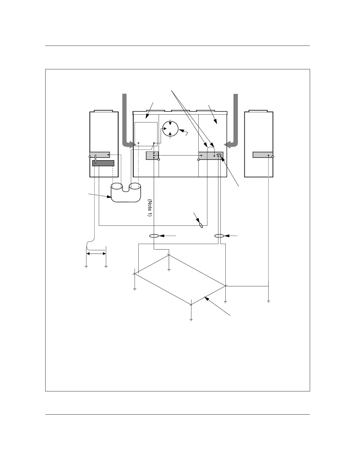
Figure 3-5
AN2016 system ground block diagram
AN0104.eps
L1
L2
6 AWG bonding
100 amp
AC service
Power
pedestal
SPC and termination
compartment
AN 2016 cabinet
X-connect
G
All dielectric fiber
cables entering
through here
Bending radius > 8 in.
and no less than 90
0
Lug terminals
approved for the
purpose
AC compartment
AC surge
arrestor
(Note 2)
All OSP Cu cables
from X-connect
entering here
G
G
G
N
N
AC cable
conduit
4 wires: L1,
L2, N, G
Two 8 ft. rods
separated by 6 ft.
Objective: <25 ohm
Designed for <25 ohm
Ground rods at least
30 in. deep and below
frost line. No less than
6 feet apart.
Ground ring- 2 AWG
solid bare tinned copper
designed for <5 ohm
2 AWG
2 AWG
2 AWG
2 AWG
solid bare
tinned copper
2 AWG
solid bare
tinned copper
Bonding wire
2 AWG (insulated)
per NEC 250-71(b)
G
Note 1:
This ground wire must be added only when the power pedestal is more than
5 feet away from the cabinet.
Note 2:
Connect a UL Listed and/or CSA Certified AC surge arrestor to the AC load center
in the following conditions: when no surge arrestor installed in the power pedestal or when
power pedestal is more than 5 feet from the cabinet.
100 A
AC load
center