3-10
Installation guidelines
AN2016 Cabinet User Guide Rel 1.0 Standard May 1999
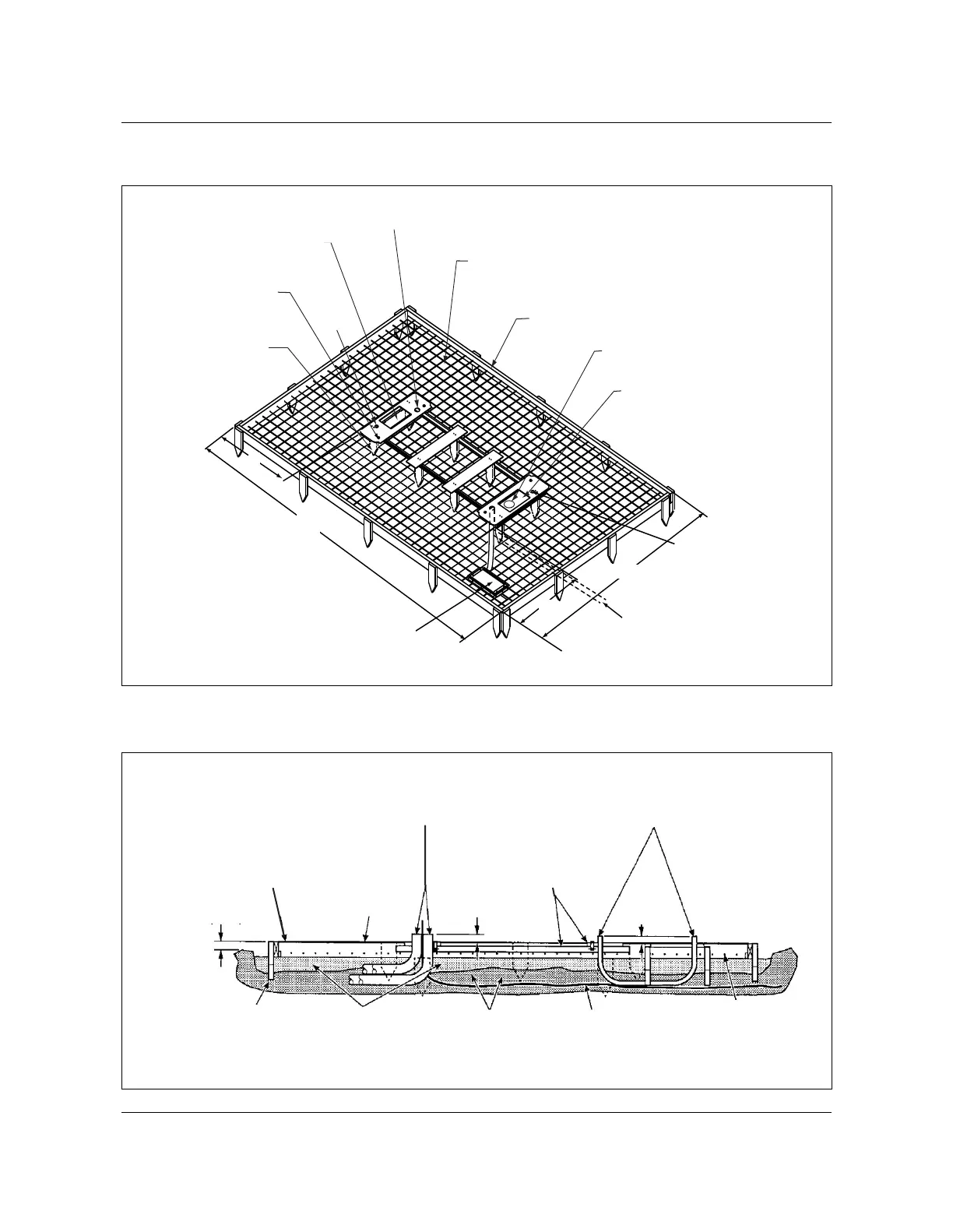
Figure 3-3
Foundation pad
AN0008.eps
Figure 3-4
Position of conduit in template
AN0029.eps
Template fastened to
16" wooden stakes
(typical at corners)
172"
106"
Anchor bolt concrete
insert (typ. 4 places)
10" x 17" cable entry box for
termination compartment.
Do not allow concrete to enter.
AC electrical conduit extending
2" above concrete pad.
Welded wire mesh
6 x 6 x 6/6 (6 ga. wire) or
6 x 6 x 4/4 (4-ga. wire)
2 x 5 concrete form
10" x 17" cable entry box
for AC cable. Do not allow concrete
to enter if cables are to routed
into chamber. If no cable entry
is planned, fill box with concrete.
Refer to Fig. 3-22 for
AC power cable entrance
29 7/8"
Optional power
transfer pedestal
mounting template.
27 7/8"
Optional pipe routing
to other power supply.
Hole for ground
Hole for
Ground
Cable conduits 2 in.
above concrete pad
Cabinet templates flush
with, to 1/4 in. above
top of concrete
Ground wire to
grounding system
Welded mesh
6 x 6 x 4/4
(4 gauge wire)
Compacted
soil
Sand or
gravel
16 in. stakes
2 in.
(51 mm)
2 in.
(51 mm)
Wooden form
(2 x 6) typical
6 in. concrete
pad
Electrical conduit extending
2 in. above concrete pad