$SSOLFDWLRQV
Combination Fire/Security Applications
5-10 AFP-300/AFP-400 Installation PN 50253:C1 05/22/97
,QVWDOOLQJ D 6HFXULW\
7DPSHU 6ZLWFK LQWR WKH
&$%;
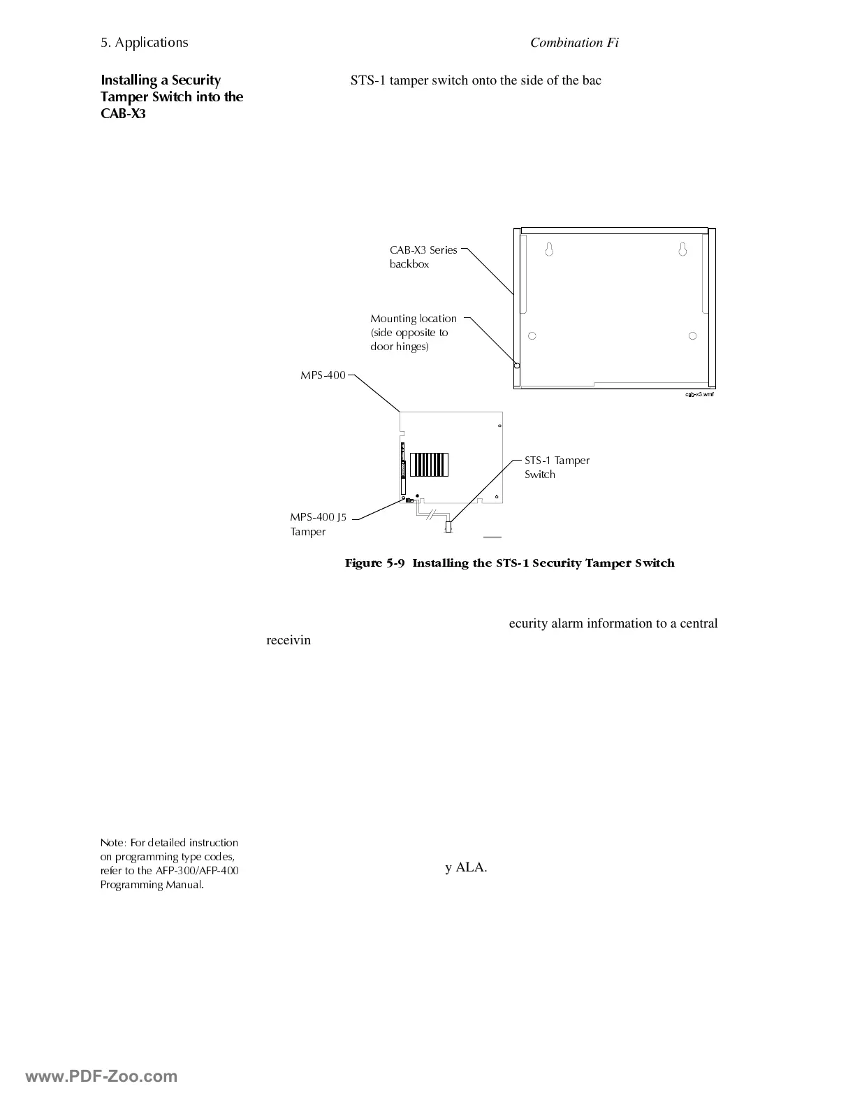
1. Install the STS-1 tamper switch onto the side of the backbox opposite the door
hinge.
2. Push the STS-1 through the opening in the backbox until the switch snaps into
place.
3. Install the magnet on the same side of the cabinet door as the lock. Push the
magnet through the opening in the door until the magnet snaps into place.
4. Connect the STS-1 connector to J5 (Tamper) on the MPS-400.
)LJXUH ,QVWDOOLQJ WKH 676 6HFXULW\ 7DPSHU 6ZLWFK
5HFHLYLQJ8QLW
For applications requiring transmission of security alarm information to a central
receiving unit, the control panel may be connected to an AM-2020 or AFP-1010
provided with a NIB-96 network interface board. (For wiring information, refer to
Appendix B.) Configure the AM2020/AFP1010 for Combination Fire/Security
applications as outlined in the installation section of the AM2020/AFP1010 manual.
Security alarm zones are reported to the AM2020/AFP1010. through the NIB-96.
Program AM2020/AFP1010 networked monitor points as a SARM type code (security
alarm).
3URJUDPPLQJ
The control panel can communicate with any number of Security ALA type code
devices. To do so, program the points as follows:
1RWH )RU GHWDLOHG LQVWUXFWLRQ
RQ SURJUDPPLQJ W\SH FRGHV
UHIHU WR WKH $)3$)3
3URJUDPPLQJ 0DQXDO
1. Select the address of the monitor module(s) to be used for security; and
2. Set the type code to Security ALA.
0RXQWLQJ ORFDWLRQ
VLGH RSSRVLWH WR
GRRU KLQJHV
&$%; 6HULHV
EDFNER[
036 -
7DPSH U
676 7DPSHU
6ZLWFK
036
www.PDF-Zoo.com
 Loading...


