$SSHQGL[ $ $QQXQFLDWRUV
Connecting Annunciators
A-12 AFP-300/AFP-400 Installation PN 50253:C1 05/22/97
&RQQHFWLQJ$QQ XQFLDWRUV
2YHUYLHZ
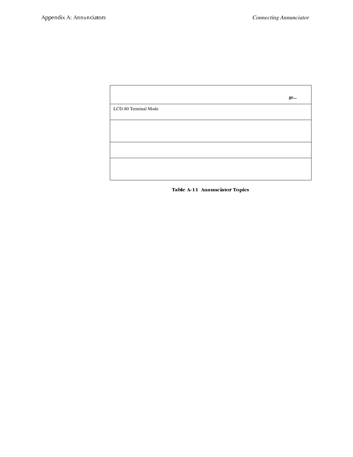
This section contains guidelines, installation instructions, and wiring diagrams for
connecting annunciator devices to the control panel. Table A-11 lists each device
covered in this section:
7DEOH $ $QQXQFLDWRU 7RSLFV
Topic Covers
Refer to
page...
LCD-80 Terminal Mode EIA-485
connections
Connecting an LCD-80 in terminal mode,
to the CPU.
A-13
LCD-80 ACS Mode EIA-485
Connection (CPU, TB4)
Connecting an LCD-80 in Terminal Mode,
the LCD-80 connects to TB4 on the CPU
using a looped EIA-485 circuit.
A-14
Powering ACS-, ACM-, and LDM-type
Annunciators
Connecting an LCD-80 operated in ACS
mode to TB3 on the CPU.
A-15
ACS and LDM Series EIA-485
Connection
Connecting an ACS series annunciator,
including the LDM-80), to TB4 on the CPU
using an EIA-485 circuit.
A-16
www.PDF-Zoo.com
 Loading...


