Power-limited Modules and Circuits
$SSHQGL[ ) 8/ 3RZHUOLPLWHG :LULQJ 5HTXLUHPHQWV
AFP-300/AFP-400 Installation PN 50253:C1 05/22/97 F-3
3RZHU6XSSO\:LULQJ
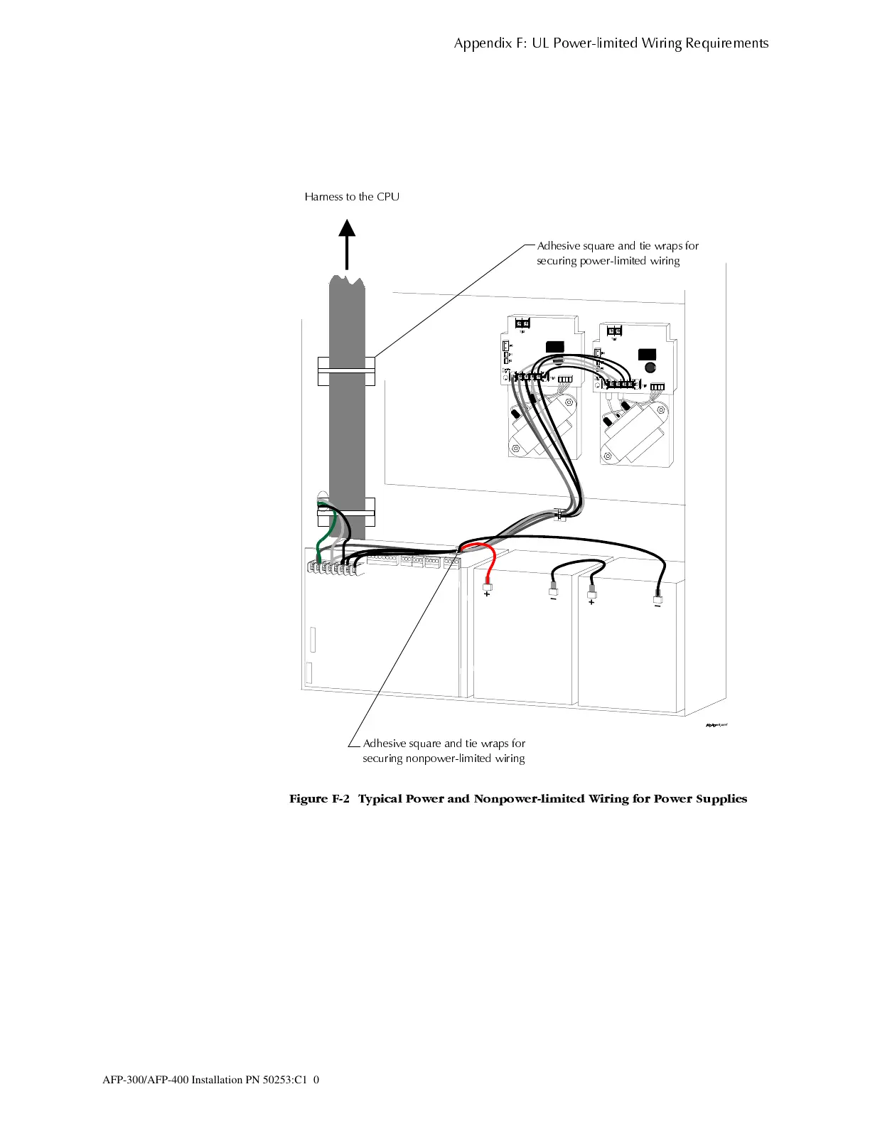
AC and battery wiring are not power-limited. Maintain at least 0.25 inches between
power-limited and nonpower-limited circuit wiring. Install tie wraps and adhesive
squares to secure the wiring. Figure F-2 shows a typical wiring diagram for a power
supply:
)LJXUH ) 7\SLFDO 3RZHU DQG 1RQSRZHUOLPLWHG :LULQJ IRU 3RZHU 6XSSOLHV
$GKHVLYH VTXDUH DQG WLH ZUDSV IRU
VHFXULQJ SRZHUOLPLWHG ZLULQJ
$GKHVLYH VTXDUH DQG WLH ZUDSV IRU
VHFXULQJ QRQSRZHUOLPLWHG ZLULQJ
+DUQHVV WR WKH &38
www.PDF-Zoo.com
 Loading...


