$SSHQGL[ ) 8/ 3RZHUOLPLWHG :LULQJ 5HTXLUHPHQWV
Power-limited Modules and Circuits
F-2 AFP-300/AFP-400 Installation PN 50253:C1 05/22/97
8/3RZHUOLPLWHG:LULQJ5HTXLUHPHQWV
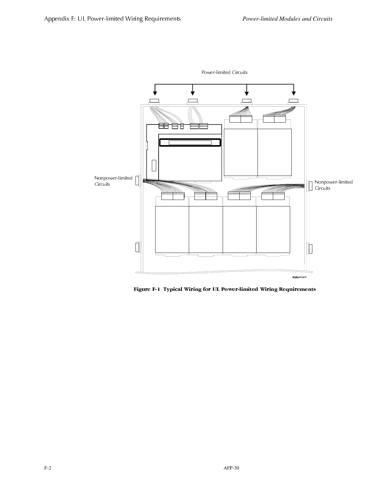
Figure F-1 shows a typical wiring diagram for the control panel. The first two rows
show rows of modules configured with at least a 0.25 inch separation between
power-limited and nonpower-limited wiring.
)LJXUH ) 7\SLFDO :LULQJ IRU 8/ 3RZHUOLPLWH G :LULQJ 5HTXLUHPHQWV
3 RZHUOLPLWHG &LUFXLWV
1RQSRZHUOLPLWHG
&LUFXLWV
1RQSRZHUOLPLWHG
&LUFXLWV
www.PDF-Zoo.com
 Loading...


