,QVWDOODWLRQ
Installing a 4XTM Module (Remote Station Fire Alarm)
2-22 AFP-300/AFP-400 Installation PN 50253:C1 05/22/97
,QVWDOOLQJD;700RGXOH5H PRWH 6WDWLRQ)LUH$ODUP
0RXQWLQ
WKH0RGXOH
Install the 4XTM module by following these steps:
Table 2-9 Mounting a 4XTM Module
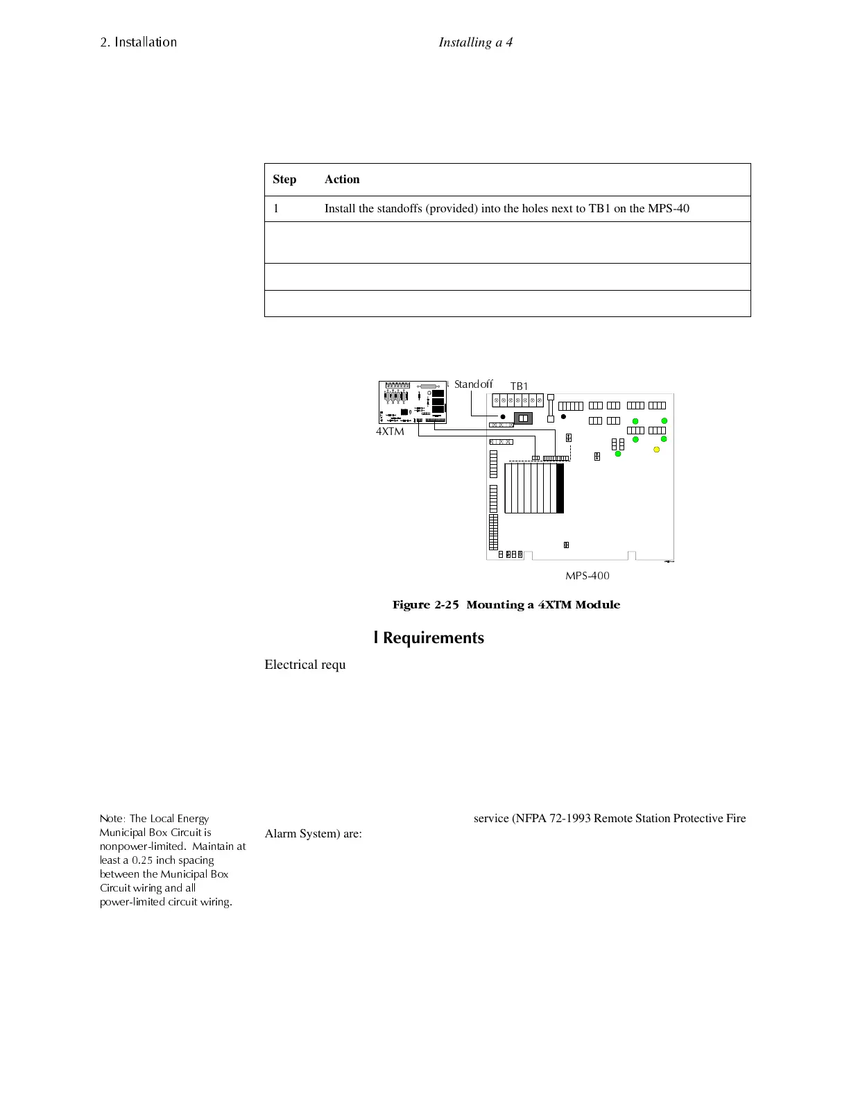
Figure 2-25 shows where to mount a 4XTM module on the MPS-400 board:
)LJXUH 0RXQWLQJ D ;70 0RGXOH
;70(OHFWULFDO5H
XLUHPHQWV
Electrical requirements for local energy municipal Box service (NFPA 72-1993
Auxiliary Protective Fire Alarm System) are:
1RWH 7KH /RFDO (QHUJ\
0XQLFLSDO %R[ &LUFXLW LV
QRQSRZHUOLPLWHG 0DLQWDLQ DW
OHDVW D LQFK VSDFLQJ
EHWZHHQ WKH 0XQLFLSDO %R[
&LUFXLW ZLULQJ DQG DOO
SRZHUOLPLWHG FLUFXLW ZLULQJ
Electrical requirements for remote station service (NFPA 72-1993 Remote Station Protective Fire
Alarm System) are:
Step Action
1 Install the standoffs (provided) into the holes next to TB1 on the MPS-400 board.
2 Carefully align the pins on the MPS-400 PC board with the connector on the 4XTM
board.
3 Press firmly on the 4XTM board until the board locks in place on the standoffs.
4 Screw the 4XTM board to the standoffs.
Supervisory current 5.0 mA
Trip current 0.35 A (subtracted from NAC power)
Coil voltage 3.65 VDC
Coil resistance 14.6 ohms
;70
036
7%
6WDQGRII
Wire resistance (panel and trip coil) Maximum of 3.0 ohms
Maximum load for each circuit 10 mA
Reverse polarity output voltage 24 VDC (nominal) 28 VDC (max)
www.PDF-Zoo.com
 Loading...


