Connecting Annunciators
$SSHQGL[ $ $QQXQFLDWRUV
AFP-300/AFP-400 Installation PN 50253:C1 05/22/97 A-13
/&'7HUPLQDO0RGH(,$&RQQHFWLRQ&387%
&RQQHFWLRQ *XLGHOLQHV
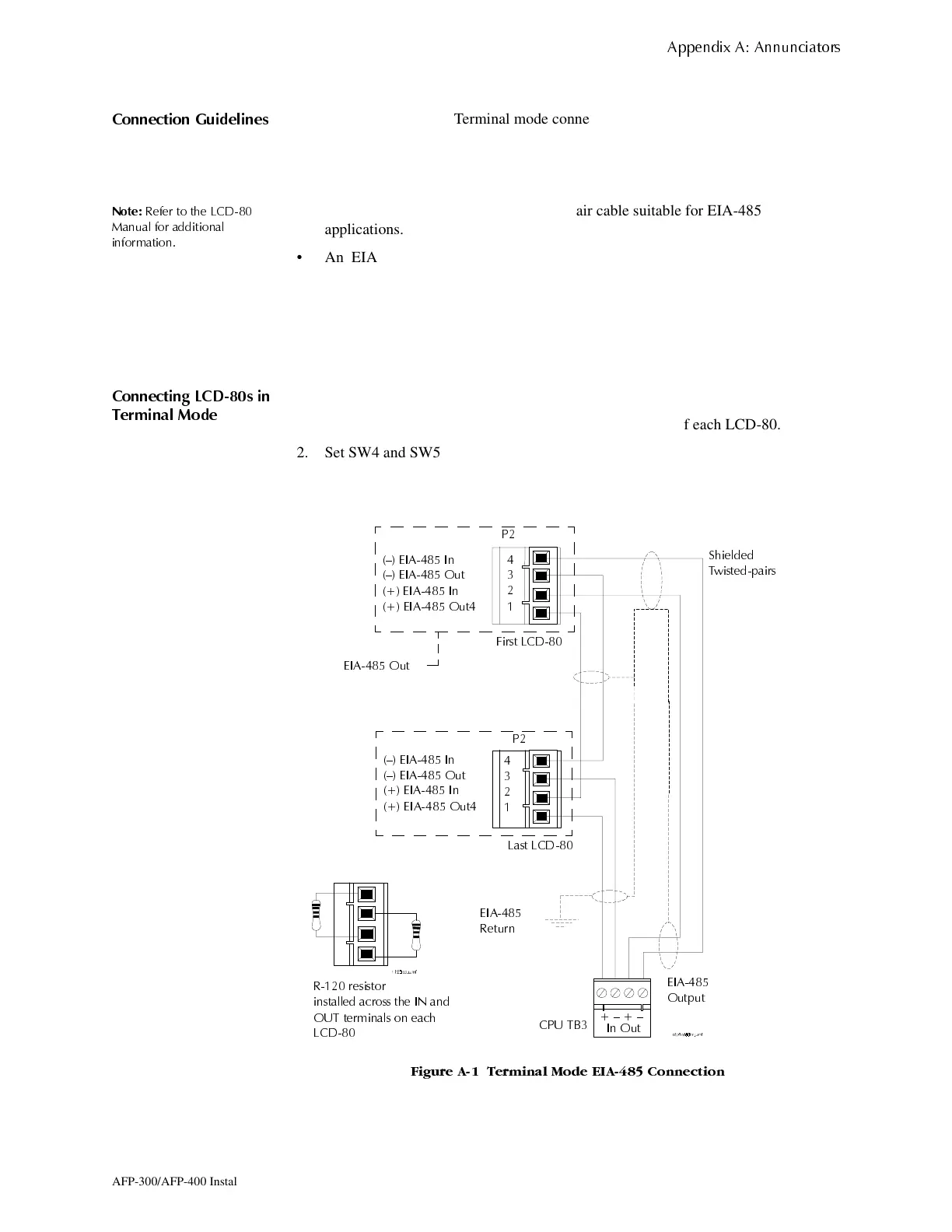
An LCD-80 operating in Terminal mode connects to TB3 on the CPU using a looped
power-limited and supervised EIA-485 circuit as shown in Figure A-1.
• Maximum distance between the control panel and the first or last LCD-80 and
between each LCD-80: 6,000 feet (using 16 AWG wire).
1RWH
5HIHU WR WKH /&'
0DQXDO IRU DGGLWLRQDO
LQIRUPDWLRQ
• Use overall foil/braided-shield twisted-pair cable suitable for EIA-485
applications.
• An EIA-485 circuit is rated at 5.5 VDC max., 60 mA max.
• For non-English language systems, LCD-80 standby current equals the alarm
current (100 mA).
• Each LCD-80 must connect to regulated 24 VDC power. Power an LCD-80 from
the MPS-400 power supply or a separate UL-listed power supply (For power
connections, see Figure A-3 on page A-15.)
&RQQHFWLQJ /&'V LQ
7HUPLQDO 0RGH
Set LCD-80 DIP switches as follows:
1. Install R-120 resistors across the IN and OUT terminals of each LCD-80.
2. Set SW4 and SW5 on the LCD-80 to the TERM position (SW1-7 ON).
3. Set DIP Switch SW3-1 and SW3-2 to OFF on all LCD-80s except the last LCD-80.
4. Set SW3-1 and SW3-2 to ON on the last LCD-80.
)LJXUH $ 7HUPLQDO 0RGH (,$ &RQQHFWLRQ
² (,$ ,Q
² (,$ 2XW
(,$ ,Q
(,$ 2XW
² (,$ ,Q
² (,$ 2XW
(,$ ,Q
(,$ 2XW
&38 7%
3
3
/DVW /&'
)LUVW /&'
6KLHOGHG
7ZLVWHGSDLUV
²²
,Q 2XW
(,$
2XWSXW
(,$
5HWXUQ
(,$ 2XW
5 UHVLVWRU
LQVWDOOHG DFURVV WKH ,1 DQG
287 WHUPLQDOV RQ HDFK
/&'
www.PDF-Zoo.com
 Loading...


