$SSHQGL[ $ $QQXQFLDWRUV
Connecting Annunciators
A-14 AFP-300/AFP-400 Installation PN 50253:C1 05/22/97
/&'$&60RGH(,$&RQQHFWLRQ&387%
&RQQHFWLRQ *XLGHOLQHV
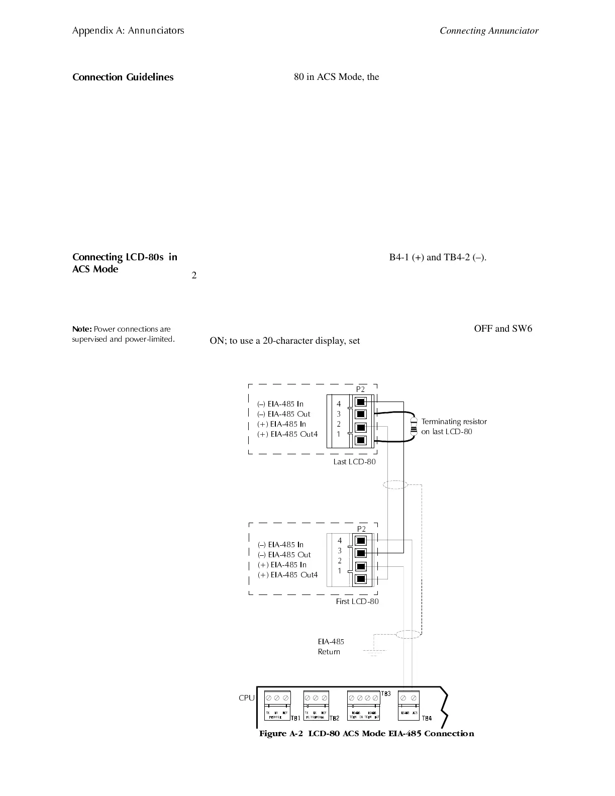
When operating an LCD-80 in ACS Mode, the LCD-80 connects to TB4 on the CPU
using a looped EIA-485 circuit as shown in Figure A-2.
• EIA-485 circuits are power-limited and supervised.
• LCD-80s require connection of operating power.
• Maximum distance between the control panel and the first or last LCD-80 and
between each LCD-80: 6,000 feet (using 16 AWG wire).
• If powering LCD-80s by a separate, UL-listed power supply, you can connect up to
32 devices.
• Use twisted-pair cable with a characteristic impedance of approximately 120 ohms.
• The EIA-485 circuit is rated 5.5 VDC max., 60 mA max.
• Refer to the LCD-80 Manual for additional information.
&RQQHFWLQJ /&'V LQ
$&6 0RGH
1. Connect EIA-485 power to CPU terminals TB4-1 (+) and TB4-2 (–).
2. Set the LCD-80 start address to address 01.
3. Set SW2 to 1; set SW3-1 and SW3-2 to OFF.
4. Set the LCD-80 to a size of 128 points.
1RWH
3R ZHU FRQQHFWLRQV DUH
VXSHUYLVHG DQG SRZHUOLPLWHG
5. Set the character display: To use a 40-character display, set SW5 OFF and SW6
ON; to use a 20-character display, set SW5 ON and SW6 OFF.
6. Install a 120 ohm terminating resistor on the last LCD-80.
)LJXUH $ /&' $&6 0RGH (,$ &RQQHFWLRQ
² (,$ ,Q
² (,$ 2XW
(,$ ,Q
(,$ 2XW
3
² (,$ ,Q
² (,$ 2XW
(,$ ,Q
(,$ 2XW
&38
7HUPLQDWLQJ UHVLVWRU
RQ ODVW /&'
/DVW /&'
)LUVW /&'
3
(,$
5HWXUQ
www.PDF-Zoo.com
 Loading...


