4-16
Security 15088:J 10/22/99
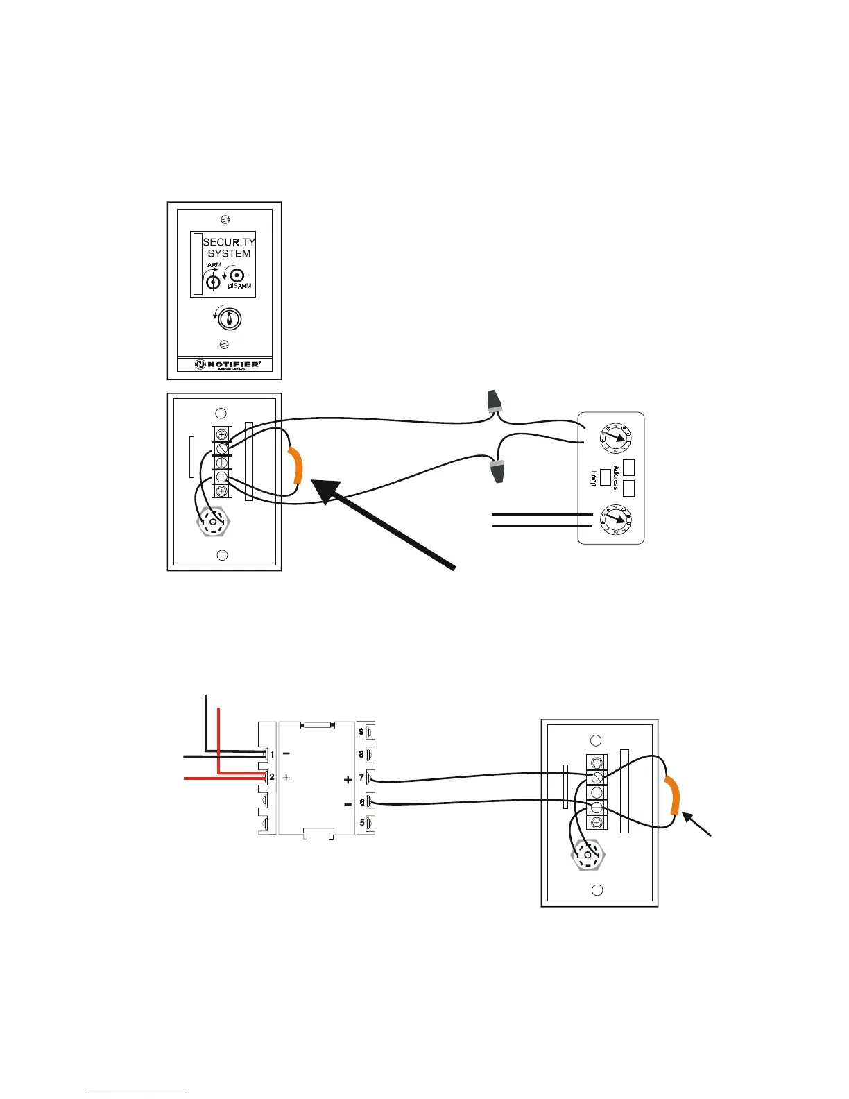
Figure 1.3-8 Connecting an MMX-1 Module to the RKS-S
1.3.1 CONNECTING AN RKS-S REMOTE KEYSWITCH
The RKS-S Remote Keyswitch arms and disarms the system. It can be mounted in a UL listed single-gang electrical
box. Both the MMX-1/MMX-101 (as shown below) or other monitor module (see Table 1.1-1 for module options) and
RKS-S must be mounted within the protected area. Figures 1.3-7 and 1.3-8, respectively, depict the connection of an
MMX-101 or an MMX-1 module to the RKS-S.
WARNING!
XP Transponder circuits (XPP-1, XPM-8, XPC-8, XPR-8, XPM-8L) are not suitable for security applications.
Figure 1.3-7 Connecting an MMX-101 Module to the RKS-S
RKS-8
front
RKS-8
rear
Yellow (-)
Purple (+)
MMX-101
Signaling
Line
Circuit
Red
Black
(-)
Wire an R-47K End-of-Line
Resistor into the circuit
(+)
Wire an R-47K
End-of-Line
Resistor into
the circuit
RKS-8
rear
MMX-1
Signaling Line
Circuit Out
Signaling
Line Circuit In
www.PDF-Zoo.com