1-58
Installation 15088:J 10/22/99
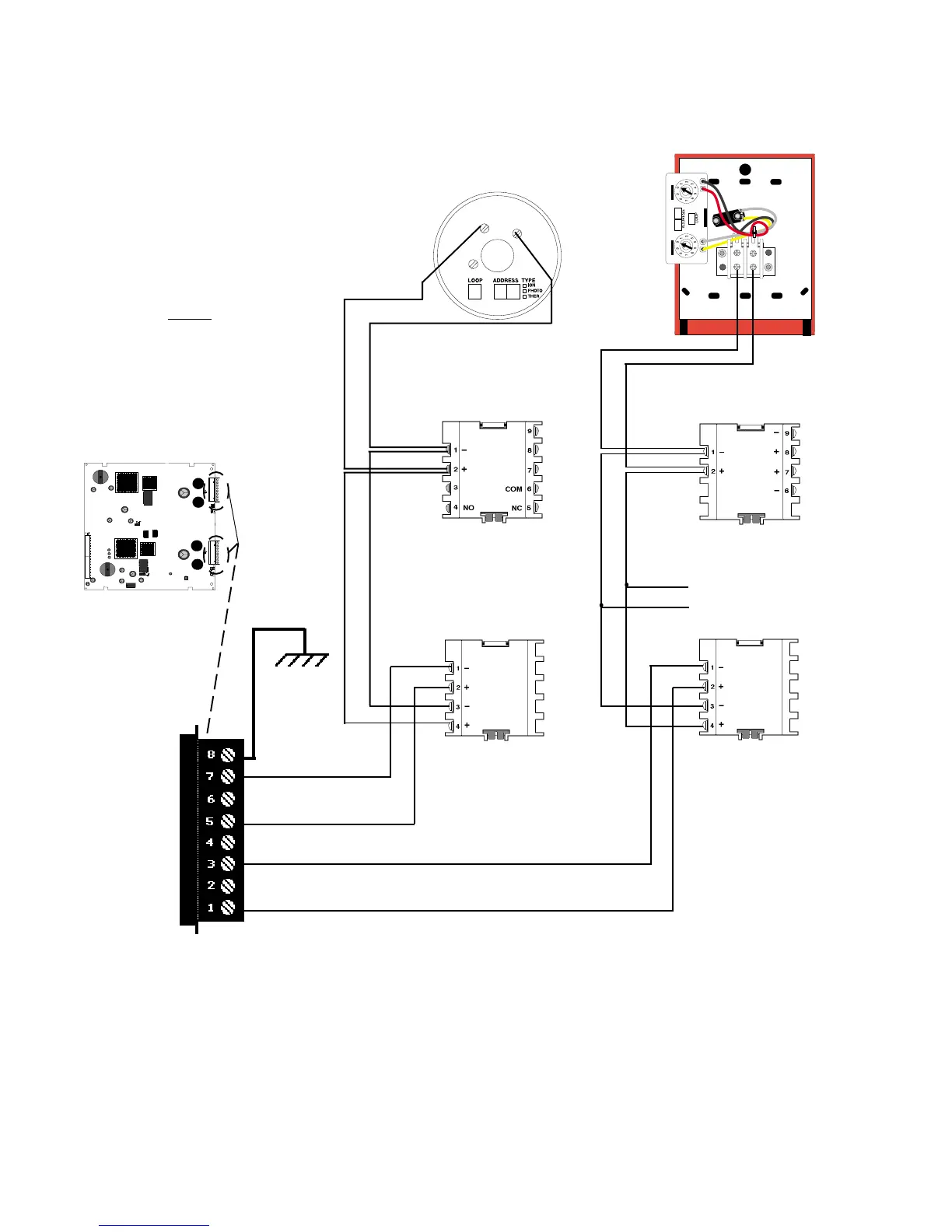
Figure 4.3-3 Typical NFPA Style 4 SLC Loops
LIB Signaling Line Circuit (SLC) loops can be wired to meet the requirements of an NFPA Style 4 (refer to Figure
4.3-3), Style 6 (refer to Figure 4.3-4) or Style 7 (refer to Figure 4.3-5) SLC.
Connect to
chassis via
Cable 71073.
Detectors
Separate T-Tap to
other Loop
devices
ISO-X
ISO-X
2(+)
1(-)
3
Modules
Pull Stations
Modules
All terminals are power-limited
LIB
SLC Loop
Earth Ground
Channel B (-)
no connection
Channel B (+)
no connection
Channel A (-)
no connection
Channel A (+)
LIB
NOTE
Refer to Appendix A and
installation drawings supplied
with each loop device for rating
and specification information.
Note: Isolator devices are
not required for the Style 4
configuration. See "Device
Loading and Isolator Power
up". With Style 4 wiring
multiple branches can be
made at the LIB, each
protected by an isolator
device. This illustration
depicts two independent
Style 4 SLC loops.
Removal of either of the two
isolator modules results in a
single Style 4 SLC loop.
www.PDF-Zoo.com