1-78
Installation 15088:J 10/22/99
Section 4.10 Smoke Detector Installation
The B501, BX-501, B210LP, and B501BH provide the connection between the control panels SLC Loop and
SDX-551/551H/551HT/751, CPX-551/751, the IPX-751 and the FDX-551/551R intelligent detectors.
Installation (refer to Figure 4.10-1)
1) Connect the SLC Loop to the base, Terminal 1 (-) and Terminal 2 (+).
2) If employing an RA400Z Remote LED Annunciator, connect the RA400Z positive terminal to base Terminal
3 and the negative terminal to base Terminal 1.
3) Before installing the appropriate intelligent detector head, set a unique detector SLC address on the head
with a small flat-blade screwdriver. Mark this address on the base and on the head.
4) Fit the head over the base and applying light pressure, turn the head into the base until connection is made.
5) The sensor base includes a tamper-proof feature that, when activated, prevents the removal of the sensor
without the use of a tool. Refer to the installation instructions, included with each base, for further details.
The smoke detector base is supervised and power-limited. Refer to Appendix A for SLC ratings. Wiring
examples of the B524BI/B224BI Isolator Base and the B524RB Relay Base are detailed in Figures 4.10-2 and
4.10-3, respectively.
When no relay or sounder bases are used between a pair of B524BI(A) and/or B224BI(A) isolator bases, a
maximum load of 25 addressable devices can be connected to insure that the isolators power up correctly. When
relay or sounder bases are used between isolator bases, the maximum number of addressable devices in
between the isolator bases is seven.
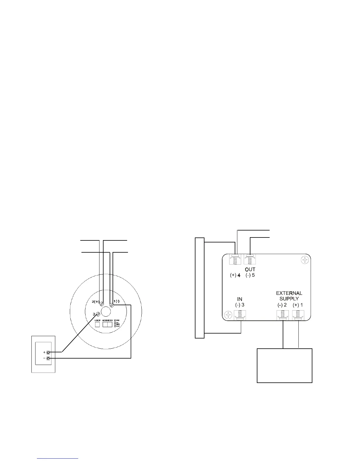
Figure 4.10-1 Wiring the Smoke Detector Base
RA400Z Remote
LED Annunciator
B501 or BX-501 Detector Base
Channel (+)
Channel ( -)
Channel (+)
Channel ( - )
to next device on
SLC Loop
SLC Loop
B501BH Detector Base
MPS-24A, FCPS, or
APS-6R power supply
+
-
to next device
Common + 24VDC
+ SLC
- SLC
LIB
+
-
www.PDF-Zoo.com