1-60
Installation 15088:J 10/22/99
2
2
2
2
2
2
2
2
2
2
2
2
2
2
2
2
2
2
2
2
2
2
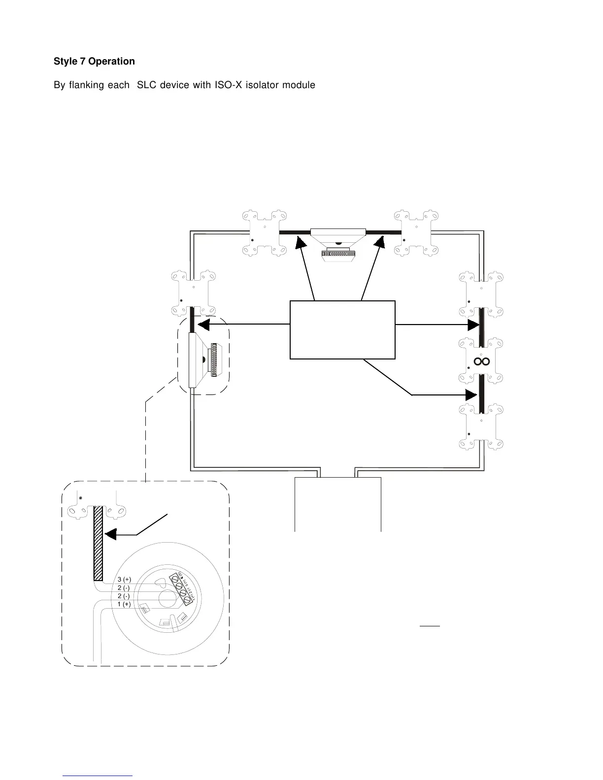
Style 7 Operation
By flanking each SLC device with ISO-X isolator modules and/or isolator detector bases, each device is
protected from an open or short on the SLC. In Figure 4.3-5 below, the MMX monitor module or XP transponder,
the non isolator-based device, and the isolator-based device will continue to function if there is an open or short
on the SLC.
The isolator-based device pictured below requires only one ISO-X module, as the isolator bases B524B1(A) and
B224B1(A) act as isolators. However, if the short circuit occurs on the wiring connected to terminals 2 and 3 of
the isolator base, the smoke detector in that base will not be isolated. Therefore, the conduit and ISO-X is
installed on this wiring. Refer to the isolator base wiring diagram in the figure.
Figure 4.3-5 NFPA Style 7 SLC
LIB SLC Loop
Channel
A
SSD Isolator Base
B524B1(A) or
B224B1(A)
MMX Monitor
Module or XP
Transponder
NO T-TAPPING PERMITTED
ISO-X
Isolator
Module
ISO-X
Isolator
Module
ISO-X
Isolator
Module
ISO-X
Isolator
Module
ISO-X
Isolator
Module
Conductors must be in
conduit.
Isolators must be within
20 feet ( 6.1m) of the
addressable device.
20 foot (6.1m)
conduit maximum
Note
When more than 100 Isolator Modules/Isolator
Bases are connected to an SLC Loop, decrease
the 198 address capacity by two addresses for
every isolator in excess of 100.
Style 7 wiring for SSD Isolator Bases
B524B1(A) and B224B1(A)
Non-isolator
base
Channel
B
www.PDF-Zoo.com