1-18
Installation 15088:J 10/22/99
Section 2.4 Component Placement
Each component in the system has a specific mounting position in the cabinet. Mount any optional APS-6R
power supplies and amplifiers in CHS-4/4L chassis positions A through D as required. It is recommended that the
CHS-4/4L chassis always be installed in the lowest cabinet row available (refer to Table 2.4-1).
Table 2.4-1 Cabinet Size Information
C
ABINET
M
ODELS
C
ABINET
R
OWS
3A-BAC1
3B-BAC2
3C-BAC3
3D-BAC4
Figure 2.4-1 Component Placement Guidelines
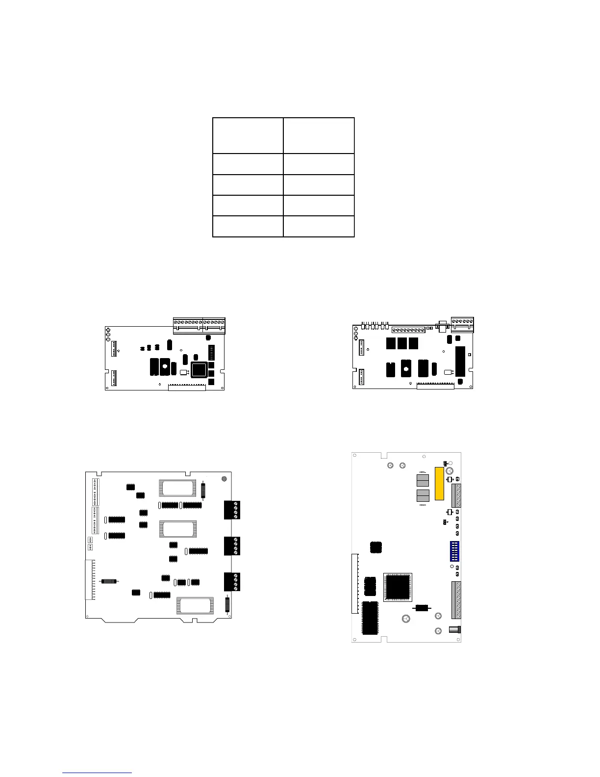
NIB-96 (Power-limited) Mounts in any one LIB position
or any two CHS-4/4L positions.
UZC-256 (Power-limited) Mounts in any one LIB position or
any two CHS-4/4L positions.
CCM-1 (Power-limited) Mounts in any one LIB position
or any two CHS-4/4L positions.
Optional component placement guidelines are provided in Figure 2.4-1.
NAM-232 (Power-limited) Mounts in either the left or right
position of a CHS-4 by using four PEM studs on the
CHS-4 chassis.
www.PDF-Zoo.com