1-68
Installation 15088:J 10/22/99
NOTES
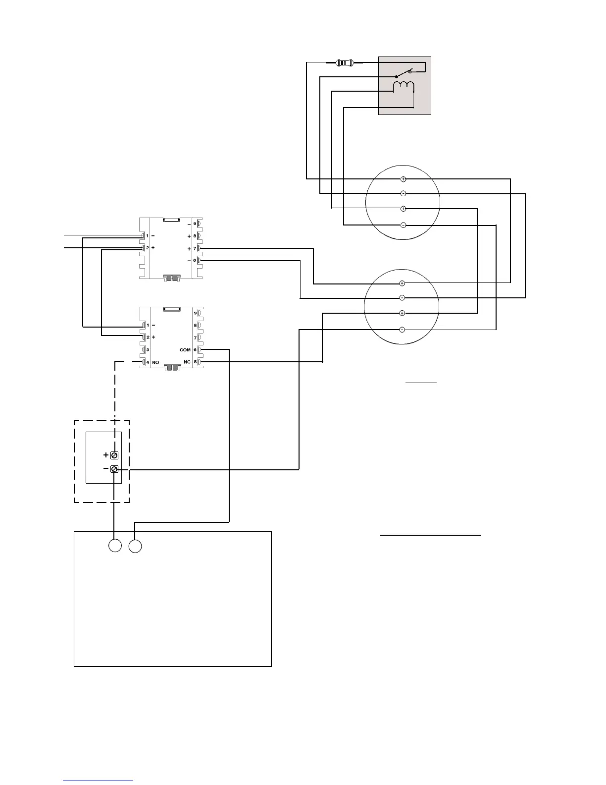
• Place End-of-Line Resistor in series with supervision
relay contacts as shown on last detector in loop.
• The power supervision relay coil leads must be
connected to the last detector base 24V screw
terminal.
• For additional ratings, refer to Appendix A.
• The CMX shown (when properly programmed)
performs the reset function for all smoke detectors
connected to the IDC.
• Maximum of 30 PWRC modules per SLC.
• Calculation of the maximum allowable resistance in
the 24V DC smoke detector power wiring:
(20.6 - Vom)
(N)(Is) + (NA)(Ia) + (Ir)
where:
Rmax- is the maximum Resistance of the 24V
wires.
Vom - is the minimum operating voltage of the
detector or end-of-line relay, whichever is
greater, in volts.
N - is the total number of detectors on the
supply 24V circuit.
Is - is the detector current in non-fire alarm.
NA - is the number of detectors on the 24V
power circuit which must function at the
same time in alarm.
Ia - is the detector current in alarm.
Ir- is the end-of-line relay current.
Figure 4.6-5 Employing Four-Wire Smoke Detectors (Style B IDC)
All connections are supervised and power limited
Software Type ID “SCON”
Software Type ID “PWRC”
IDC(+)
IDC(-)
24V DC (+)
Common (-)
IDC(+)
IDC(-)
24V DC (+)
Common (-)
Red
Black
- +
Break tabs
The CMX resets power to the
detectors. It is not needed for
power supplies using
resettable smoke detector
MMX-1
SLC Channel A
-
+
*
RA400Z
WARNING!
Observe proper polarity
on the RA400Z or device
will be damaged.
CMX
Listed
Power
Supervision
Relay
UL listed 24V DC
Four-Wire Smoke Detectors
Power-limited
power.
The RA400Z annunciates
the reset of smoke
detector power. It is
optional.
*47K ELR, 1/2-watt Part Number A2143-00
UL listed 24 VDC Regulated Power
Limited Power Supply for Fire Protective
Signaling
or
MPS-24A/E, TB3 Terminal 1 (+) and 2 (-)
APS-6R, TB2 Terminal 1 (+) and 2 (-)
Terminal 3 (+) and 4 (-
)
Rmax =
Note: contacts shown
in the energized
condition.
www.PDF-Zoo.com