RECEIPT, INSTALLATION AND START-UP OP–2FM OWNER'S MANUAL
NU–VU® FOOD SERVICE SYSTEMS PO BOX 35 MENOMINEE, MICHIGAN 49858-0035
page 4 SALES FAX (906) 863-5889 • SERVICE FAX (906) 863-6322 (800) 338-9886
INSTALLATION:
Roll the unit into the exact position where it will be operated. Make sure there will be enough clearance on
each side of the unit so that it can be easily accessed or moved out for maintenance and service. Mark the
locations of the electrical and optional water connections on the wall.
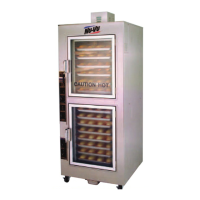
Check the swing of both the Oven and Proofer Doors, making sure they have enough room to open
completely without hitting anything or obstructing the work area. Also check the Door hinging of the unit.
If you desire to change the hinging for any reason, you should follow the procedure outlined in the
SERVICE AND REPLACEMENT GUIDE under DOOR HINGING, How to Change.
Move the unit out of its operating position and proceed with the service connections.
Electrical Connections - -
Check to determine that the power source is the same voltage and phase as that indicated on the label on
the side of the unit. If the voltage and/or phase is not the same, please call NU-VU
®
for instructions on
changing the voltage and/or phase of your equipment.
Your licensed installer or electrician should remove the exterior Side Access Panel on the control side of
the unit to expose the power terminal connections. A wiring schematic is attached to the inside of the unit
near the power terminal connections.
This unit must be connected in accordance with all national and local electrical codes. All electrical
connections must be made with COPPER WIRE ONLY in the correct gauge for the application. The unit
may be connected either through a plug and receptacle-type connection or by direct wiring. Allow enough
slack in the wiring to allow for equipment to be moved during installation or any required maintenance and
servicing.
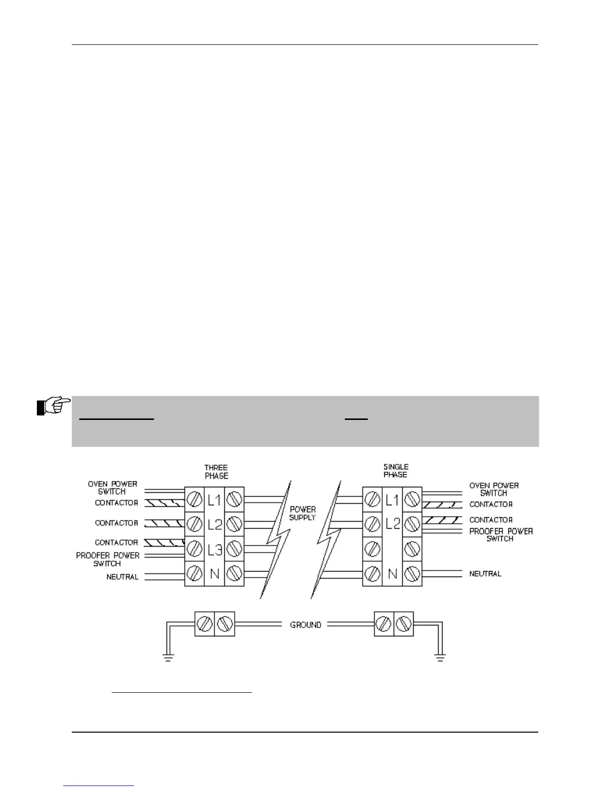
Fig. #2 – POWER SUPPLY CONNECTIONS
IMPORTANT: ALL POWER MUST BE TURNED OFF AT THE WALL BREAKER
WHILE THE UNIT IS BEING CONNECTED!