SERVICE AND REPLACEMENT GUIDE OP–2FM OWNER'S MANUAL
NU–VU® FOOD SERVICE SYSTEMS PO BOX 35 MENOMINEE, MICHIGAN 49858-0035
page 36 SALES FAX (906) 863-5889 • SERVICE FAX (906) 863-6322 (800) 338-9886
C. Disconnect the wires one at a time and
install them on the new Micro Switch. Make
sure all connections are clean and tight.
D. Turn one mounting nut onto the Micro
Switch until it is approximately half-way
down the threaded shaft.
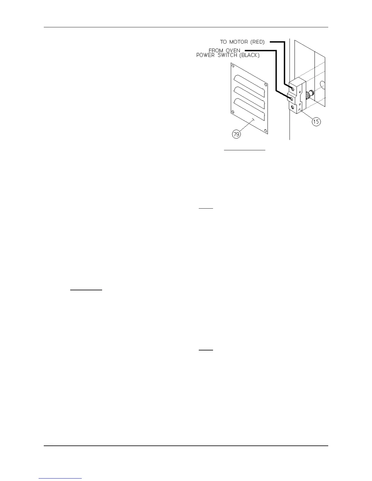
E. Position the Micro Switch in the Door jamb
and install the second mounting nut until it is
flush with the end of the threaded shaft.
Now turn the first nut finger tight until the
Micro Switch is snug in the Door jamb.
F. Check the Micro Switch position adjustment
by opening and closing the Oven Door [41].
The Micro Switch should "click" on and off
as the Oven Door [41] is opened and closed.
Gently tighten the outside mounting nut when the Micro Switch is properly positioned.
G. Carefully replace any disturbed Oven insulation, the Side Access Panel and/or the Micro Switch
Cover Plate.
H. Restore electrical power to the unit and test the Door Micro Switch for proper operation.
INDICATOR LIGHT, How To Replace:
MAKE SURE ALL POWER TO THE UNIT IS OFF. FAILURE TO DO SO MAY CAUSE
SEVERE EQUIPMENT DAMAGE OR PERSONAL INJURY!
The Indicator Lights tell when a system or control is activated. Failure of the Indicator Light itself will
not affect the operation and performance of your equipment.
A. Remove the two mounting screws on the Control Access Panel [73 or 74] and gently pull the
Control Access Panel toward you.
B. Tag and disconnect the wires on the defective Indicator Light.
C. Remove the defective Indicator Light by pushing it out the front of the Control Access Panel.
D. Install the replacement Indicator Light, wires first, from the front of the Control Access Panel
until the metal collar on the Indicator Light is tight against the front of the panel.
WARNING: Do not pull on the Indicator Light wires while installing the Indicator Light.
E. Refasten the wire connections. Make sure all connections are clean and tight.
F. Replace the Control Access Panel and secure it with the two mounting screws. Be careful not
to pull or pinch any wires when replacing the Control Access Panel.
G. Restore electrical power to the unit and test the Indicator Light and its associated Controls.
REPEAT CYCLE TIMER, How To Replace:
MAKE SURE ALL POWER TO THE UNIT IS OFF. FAILURE TO DO SO MAY CAUSE
SEVERE EQUIPMENT DAMAGE OR PERSONAL INJURY!
A. Remove the two mounting screws on the Proofer Control Access Panel [74] and gently pull the
Control Access Panel toward you.
B. Locate the Repeat Cycle Timer [83] mounted directly below the Proofer Temperature Control
Circuit Board [8] (refer to Figure #15 on page 37). Label and disconnect all wiring to the Repeat
Cycle Timer.
C. Remove the slotted mounting screw in the center of the Repeat Cycle Timer and remove the
Timer from the Proofer.