OP–2FM OWNER'S MANUAL SERVICE AND REPLACEMENT GUIDE
NU–VU® FOOD SERVICE SYSTEMS PO BOX 35 MENOMINEE, MICHIGAN 49858-0035
(800) 338-9886 SALES FAX (906) 863-5889 • SERVICE FAX (906) 863-6322 page 31
3. To increase the temperature inside the Oven or Proofer carefully rotate the index line on
the clear dial clockwise. Each "click" of adjustment is equal to approximately 5
°
of
temperature change in the Oven and 2
°
of temperature change in the Proofer. To decrease
the inside temperature rotate the clear dial counter-clockwise.
4. Gently tighten the dial screws and install the Control Knob. Check the Control setting
against the test instrument and repeat this procedure if necessary.
D. Replace the Temperature Control Sensor if this procedure fails to bring the temperature reading
within the desired range. Replace the Temperature Control Circuit Board if the temperature is
still too far off.
TEMPERATURE OR HUMIDITY CONTROL, How To Replace:
MAKE SURE ALL POWER TO THE UNIT IS OFF. FAILURE TO DO SO MAY CAUSE
SEVERE EQUIPMENT DAMAGE OR PERSONAL INJURY!
The Oven and Proofer Temperature and Humidity Controls are both replaced with the same
procedure. Only the Humidity Control in units having the AUTOMIST option is different.
Standard Controls - -
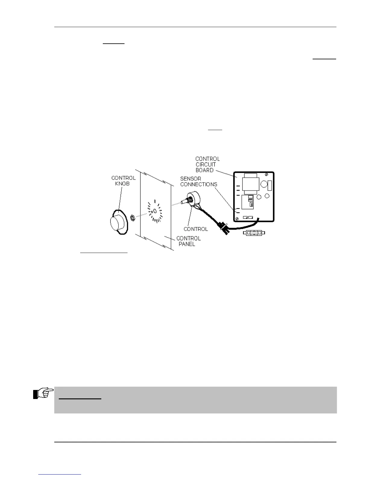
A. Remove the Control Knob by pulling it straight out from the face of the Oven Control Access
Panel [73] or Proofer Control Access Panel [74].
B. Remove the two mounting screws on the Control Access Panel, then gently pull the Control
Panel toward you.
C. Remove the retaining nut from the front of the Control and pull the Control out from behind the
Control Access Panel.
D. Label and disconnect all wiring to the Temperature or Humidity Control Circuit Board [4, 8, or
10] including the Control Sensor leads.
E. Remove the mounting screws from the corners of the Control Circuit Board and lift the Circuit
Board and Control from the unit.
F. Position the replacement Circuit Board on the mounting plate and secure it in place; seat the
mounting screws firmly but do not overtighten!
G. Position the Temperature or Humidity Control in the Control Access Panel. Secure the Control
in place with the retaining nut. Seat the nut firmly but do not overtighten!
IMPORTANT: THE CONTROL INDEXING TAB MUST BE FULLY INSERTED IN
THE TAB LOCATION HOLE IN THE ACCESS PANEL!