Installing digital modules
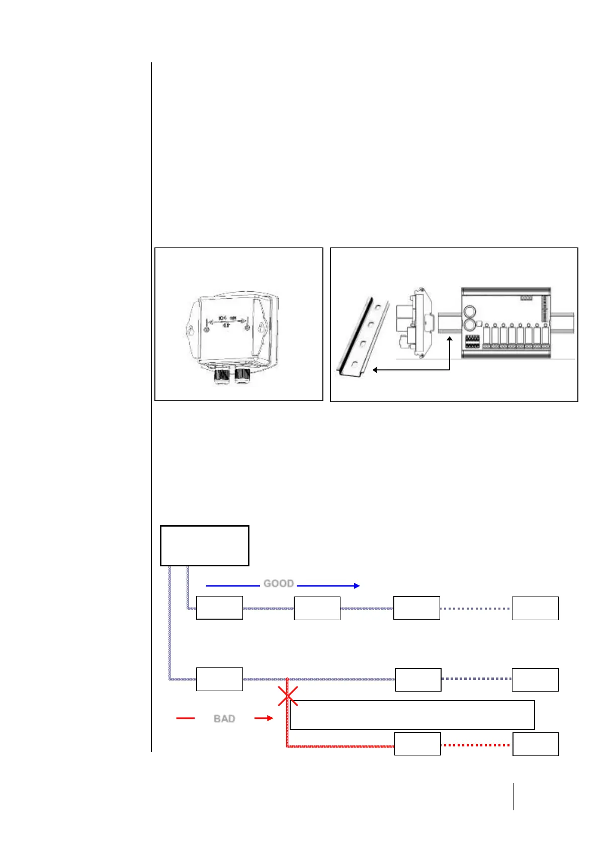
Mounting the CPS 10 sensor module
Mount the sensor modules on a flat surface using two screws (Fig. 1).
The modules should be placed in an accessible area, so that maintenance and inspection
operations can be conducted as easily and as safely as possible. Nothing in the area should
prevent the sensors from obtaining measurements of the ambient environment.
When mounting the sensor module on a vertical surface, position the cable glands on the underside
of the module to ensure proper calibration.
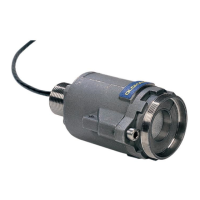
Mounting the other modules
The other modules (relay, logic input, analog output) should be mounted on a DIN rail inside of a
cabinet or an electric box. (Fig. 2).
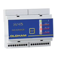
Connection of modules in a line
i IMPORTANT: All modules in a line should be wired in-line from the central controller, not in a
hub and spoke model.