Inspecting the digital buses
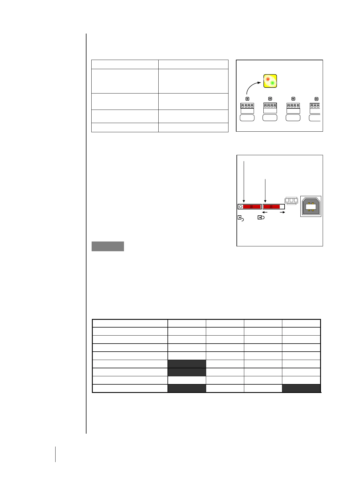
Bicolor (red/green) LEDs located above each line start, on the motherboard, allows for inspection of
the bus links as follows:
Mini-switches
Mini switch A allows the CPS controller to download and
read the user program. When the switch is in the “MEM”
position (open padlock), the user program memory is
accessible and the message “switch open” is displayed on
screen. The CPS central controller waits to download the
program from the COM_CPS software. The CPS central
controller goes into “shut-down” mode when mini switch A is
in the “MEM” position.
When the COM_CPS software programming is complete,
the mini switch should be flipped back to the “Prog” position
(closed padlock), and the central controller should be
rebooted to initialize all of the newly loaded settings.
Mini switch B only used for the central controller’s internal
microprocessor. It should always be in the “Run” position.
Internal relay and buzzer
The CPS central controller is equipped with 3 internal relays [R1, R2, R3] and a shared Buzzer.
The operating settings for the relays and the buzzer can be set with the COM_CPS software (see
table below).
The internal buzzer is activated when a specific program-defined event occurs (fault or alarm).
All lines share relays R1, R2, and R3.
The buzzer’s pitch will vary according to the alarm threshold. Alarms 1 and 2 have the same
frequency. Alarms 3 and 4 have a different pitch, allowing the operator to distinguish between alarm
levels.
The buzzer can be disconnected by removing the “buzzer activation strap” (J10) located on the
motherboard next to the buzzer (cf -: Overview of the Motherboard).
*: (System fault) alarm is triggered if there is a communication fault betweenmodules, a short-
circuit in a power supply line, or a module inversion.
X: Function can be activated or deactivated
: Default configuration setting, cannot be changed by user.