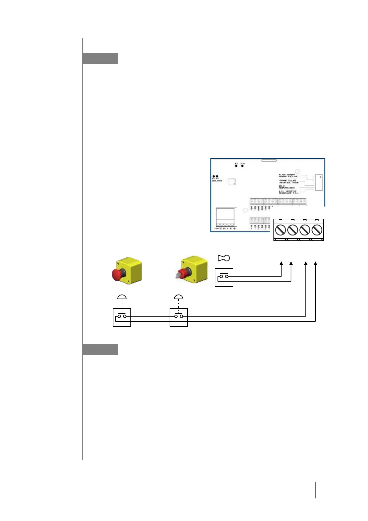
Logic Input Module
This module contains 16 logic inputs, linking priority commands, such as fire
extinguishers directly to the central controller.
A maximum of 224 total logic inputs across all modules can be activated.
Example 1: 112 modules having 8 relays each, with activated inputs.
Example 2: 7 modules with 16 logic inputs with activated inputs.
Each input can override all other commands to activate or block up to 256 relays.
Priority inputs
Two levels of input priority can be managed on each module with the COM_CPS software.
Priority inputs have control of the other inputs (all of the non-priority inputs are “blocked” when a
priority input is activated).
In the event that two different inputs of the same priority level send contradicting orders, the relay is
shut-down.
In the event of a fault, the inputs are set to
zero.
Analog Outputs Module
This module is comprised of 4 opto-isolated 4-20 mA analog outputs which can be individually
activated or deactivated.
Activated: the output analog signal (4-20 mA) varies, according to the input
Deactivated: the analog output signal will be frozen at 0mA, regardless of the input signal.
Several events can be linked to one output. In this case, the largest analog value will be recopied
onto the analog output.
The output module also has two logic inputs (LI), identical to those on the “Logic input” module.
A “slave address” for the module can be set with the “DIP” switch (DIP1).
An analog output OFF command from the central controller corresponds to 4 mA.
An analog output ON command from the central controller corresponds to 20 mA.