Configuring the communication settings
Slave address
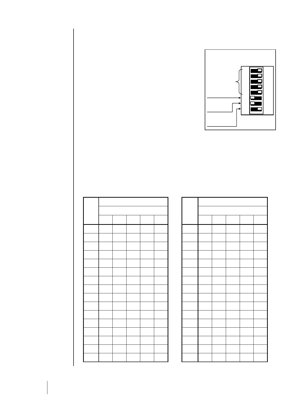
All modules in a line should be identified with a unique slave
number. Switches 1-5 on the Configuration Switches unit (Fig.
10) contained in each module, allow you to set a binary
numerical address (1…32).
Possible combinations are listed in the address table below.
Notes: The physical address of a module (1…32) should be
identical to the address recorded in the central controller
configuration program with COM_CPS.
When replacing a module, set the configuration switches in
the new module to the same position as those of the module
being replaced.
i Switches 6 (FRAME FILLING) and 7 (DELAY) should be
in the OFF position (unused options).
End of line resistor
The last module in each line should be equipped with an end of line resistor. ).
i This switch should be in the OFF position for all other modules in the line.