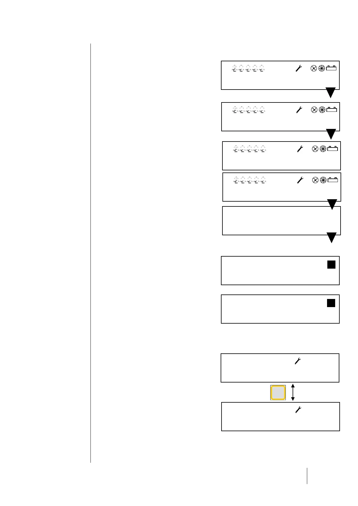
Start-up Phase
No faults or alarms are processed during the first
minute after start-up. During this phase, the
central controller runs a Checksum test (1), a
RAM test (2), a line start-up (3) and a module
mapping test with a program stored in its memory.
Voltage builds progressively in the lines. Progress
bars show the overall progress for line power-up.
Only the power-up of activated lines is shown
(identified by a diamond “ ” during the initial
power-up phase, and by a black square “ “ at
the end.)
An exclamation point “ ! “ indicates a short-circuit
line fault. The line can be reactivated through the
menu system.
Next, a sensor stabilization phase occurs (4)
during which time, the alarms are deactivated.
An inspection phase immediately follows in order
to verify that the configuration program set with
the COM_CPS software correctly maps to the
modules installed and activated.
If no errors are found, the program runs normally.
If errors are detected, the modules in question will
be flagged as faulting.
After the start-up phase, the screen will display
information pertaining to the selected mode:
events (a) or cyclic (b). The central controller
begins to process data coming in from the various
modules.
In cyclic display mode, when no alarms are
triggered the levels from each sensor are
displayed on the first line of the display screen.
In case of a power outage, the program
configuration will be saved. When the controller is
turned on, the last program installed by
COM_CPS will be loaded.
If a sensor faults, the message “Def” will replace
the reading value. If the power supply is
interrupted within a line, the two points in front of
that line will blink. Identify the problem by
touching the [ESC] key to display the error
message.
If the gas level exceeds a high or low threshold,
“Ovs” will appear on the display screen where the
value for that sensor would normally appear. This
message will display simultaneously with a
blinking arrow (pointing up or down, depending on
the situation).