Connecting Digital Modules
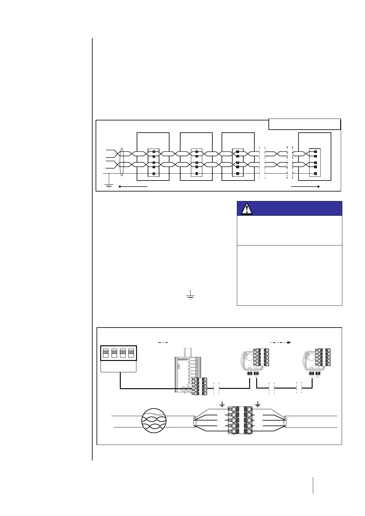
General topology of the RS-485 network
Modules are connected in “parallel” in the RS-485 network, comprised of a 1 twisted pair cable for
signals, 1 or more pairs to supply power to the modules, and 1 shield wire.
A 120 end of line resistor (EOL RESISTOR) should be placed at the last module in the line, at the
end of the bus (see Chapter 4 - End of Line Resistor).
The modules are equipped with a double connector, which can be split to easily connect conductors
and also allows you to isolate the module while maintaining line continuity.
Wiring the digital network
The sensor module has two cable glands. One
connects to the input wire, and the other connects to
the output wire which is routed to the next module.
The modules should be wired with RS-485 shielded
twisted pair cable, with a normal impedance of 100 ,
of at least 0.22mm² in diameter. +24VDC, 0V A and B
terminals are linked to +24VDC, OV terminals A and
B in other modules in the line, and then linked to the
connector corresponding to the central controller. The
cable shield should be connected to a ground
terminal marked with the following symbol:
(Fig.9).
i Do not leave any stripped wire ends exposed. To guard against electromagnetic disturbances,
the data cables and the screen (tress) cables should be cut as short as possible
Do not run cable near equipment such as
motors, transformers, or any lines
generating a large magnetic field.
Always check to ensure that the cables
are completely separated from other
circuits.