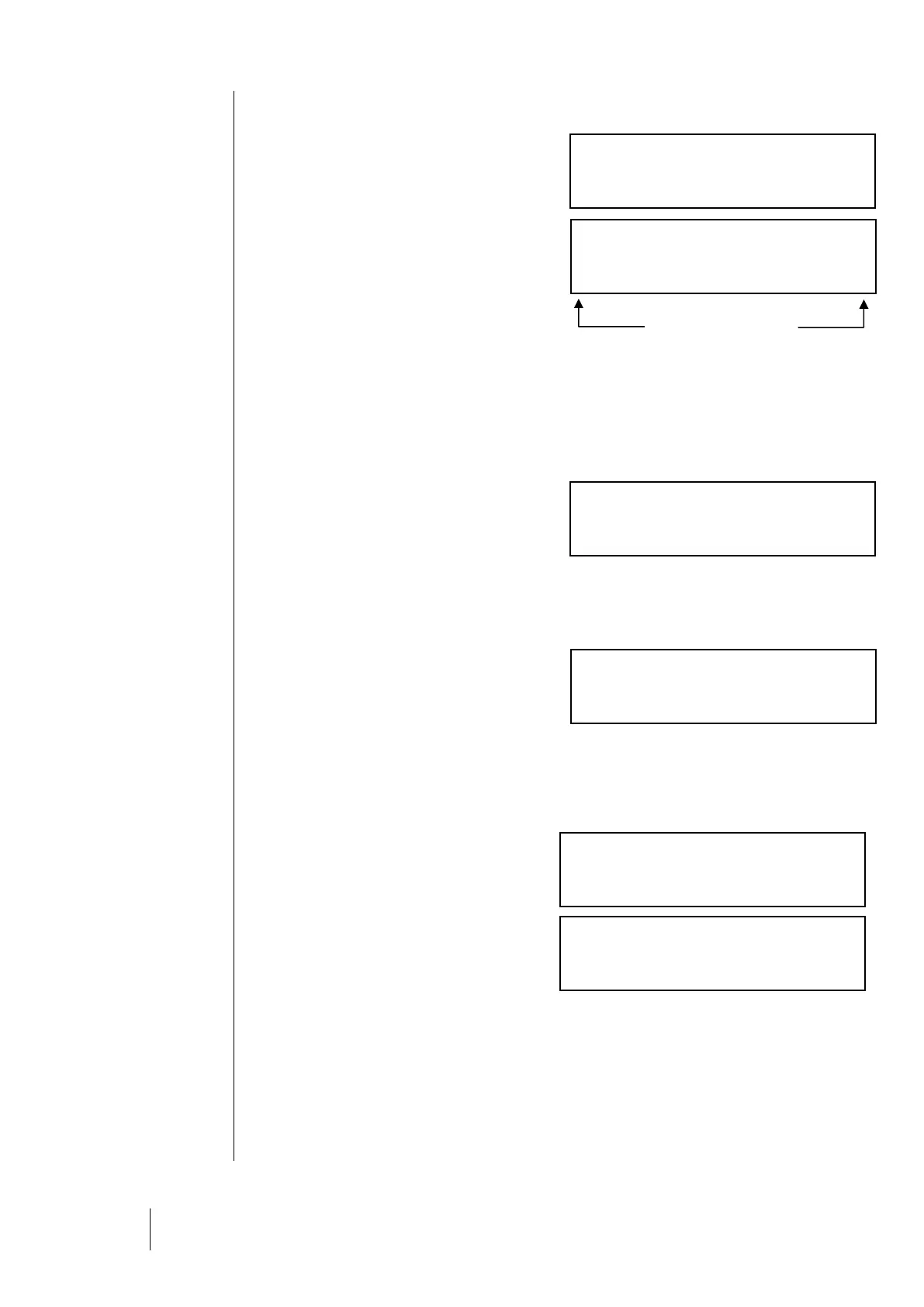
Bus Faults
This menu displays the faults from all modules in
a line. Each hexadecimal number corresponds to
a module, with Module 1 being on the left, and
Module 32 on the right.
0 = OK
1 = Communication error
2 = Module recognition error
4 = Fault triggered by a module fault word.
X = module missing or unrecognized due to a
conflict with another module
Line: 1 Module: 1 = OK
Line: 1 Module: 2 = module recognition error
Line: 1 Module: 3 = communication error
Reset maintenance
i Reserved for ISC- maintenance personnel
only.
CPS / COM_CPS Version – Available
memory level
Displays the CPS central controller version as
well as the COM_CPS programming software
version.
Displays the microcontroller availability (time)
rate (in %). This value will vary somewhat in
relation to the program but can detect if a
microprocessor is being overtaxed.
Enter the access code by using the [] [] and
[] [] keys.
Next, press the [OK] key to reinitialize all counters
to zero and to refresh the date.
CPS Installation
This menu is used to zero the following two
settings across all modules: Last zero date
Operating Time
Each module logs its operation time in days. For the sensors, this time is equal to the time since the
last calibration or the last zero.
Exceeding the scale
Each sensor logs the amount of time that levels exceed the
scale in seconds. Go to the “Module Verification” menu to see
this time.