External relay module
The relay module is available in two versions: CPS RM4 (with 4 relays) and CPS RM8 (with 8 relays).
It also has two logic inputs (LI) which can be activated.
In maximum configuration, the CPS can manage 256 relays (ex: 32 modules with 8 relays each). For
more information about the logic inputs: see: Logic inputs module.
The relays are individually programmable. The operation of each relay depends on its configuration
and its function.
Each of the 6 sensor alarms [AL1 - AL2 - AL3 - AL4 - Out of Range - Fault] can control one or more of
the 256 relays. Several events can be linked to one relay.
In case of a module relay fault, all relays of this module are restarted.
The CPS central controller will change the relay status unless they belong to a different module type.
Restarting will resolve the problem.
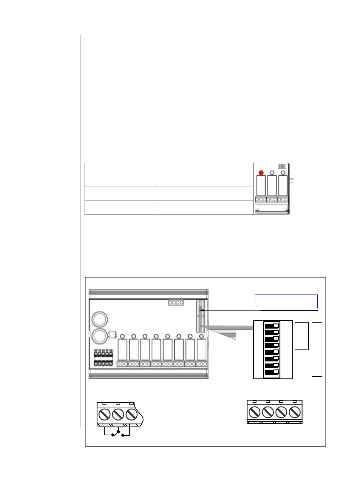
Relay status lights
Each relay has a red LED to indicate its status
Activated relay (alarm condition exists)
Non-activated relay (no alarm
condition)
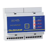
“Positive/negative” relay security
In addition to switches of CONFIGURATION, RELAY MODULES INCLUD SWITHCHES OF POISITVE AND NEGATIVE
SECURITY CONFIGURATION. Flip the switch to ON (positive security) or OFF (negative security) as
desired. Each switch acts on its corresponding relay (switch 1 relay RL1, switch 2 relay RL2, etc.).
(Fig. 11).
Note: Only switches 1-4 are active in the CPSRM4 module.
Fig. 11 : « POSITIVE / NEGATIVE » RELAY SECURITY
Output contact Relay
Minimum charge for contacts
2A / 250 VAC (Load charge)