EasyManuals Logo

Oldham CPS Series User Manual

Oldham CPS Series
76 pages
To Next Page IconTo Next Page
To Previous Page IconTo Previous Page
Page #26 background imageLoading...
Page #26 background image
Page 26
CPS User Manual
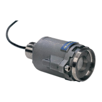
Chapter 4 Digital Modules
View of Digital Modules
RELAY MODULES CPSRM4-CPSRM8
Part
DESIGNATION
1
Power supply & network connector
2
Programmable relays ( 8 or 4 )
3
potential free RTC output contact
4
Safety switch + or - relays
5
Configuration switches (Adresses)
6
Logic Input terminals (2 Inputs)
DESIGNATION
CPS RM4
CPS RM8
RELAY MODULE
6 313 962
6 313 963
RELAY MODULE BOARD
6 451 601
6 451 602
3
5
CPS RM8
4
6
1
2
CPS RM4
LOGIC INPUT MODULE CPS AI16 ANALOG OUTPUT MODULE CPS AO4
Part
DESIGNATION
1
Power supply & network connector
2
Logic input terminal (16 Inputs)
3
Configuration switches (Adresses)
4
Module board
DESIGNATION
CPS AI16
CPS AO4
MODULE
6 313 964
6 313 980
MODULE BOARD
6 451 603
6 451 614
3
2
4
1
CPS AI16
4
1
3
SENSOR MODULE CPS 10
Part
DESIGNATION
4
Power supply & network connector
5
Configuration switches (Adresses)
6
Calibraton LED
7
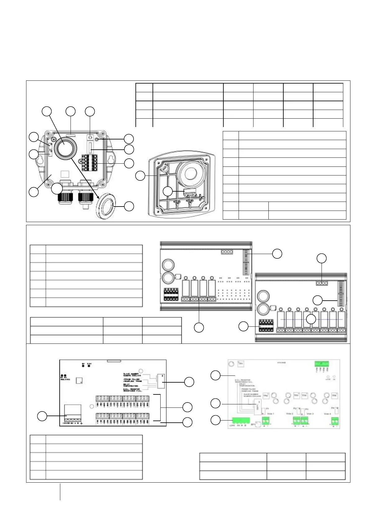
Button [sensor replacement]
8
Measurement connector [sensor replacement]
9
Sensitivity adjustment [sensor replacement]
10
Zero adjustment [sensor replacement]
11
6 153 046
CPS 10 Magnetic switch
12
6 136 052
D2 line washer (qty : 0.316)
PART
DESIGNATION
CO
NO
NO2
EXPLO
A
CPS 10 SENSOR MODULE
6 513 591
6 513 592
6 513 593
6 513 594
1
CPS 10 SENSOR
6 798 301
6 113 331
6 113 332
2
CPS 10 BOARD
6 451 597
6 451 598
6 451 599
6 451 600
3
SENSOR WASHER
6 136 243
6 136 243
6 136 243
11
12
5
4
8
A
10
9
2
6
1
3

Table of Contents

Questions and Answers:

Question and Answer IconNeed help?

Do you have a question about the Oldham CPS Series and is the answer not in the manual?

Oldham CPS Series Specifications

General IconGeneral
BrandOldham
ModelCPS Series
CategoryGas Detectors
LanguageEnglish

Related product manuals