The front panel circuit
The central controller front panel circuit is
equipped with:
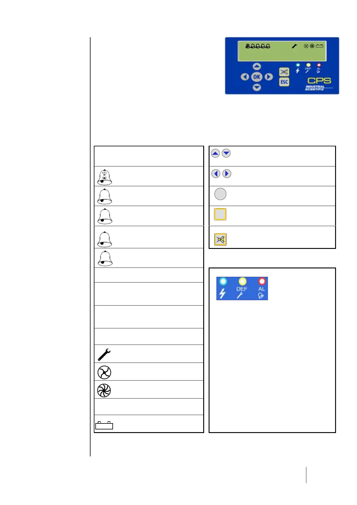
1 LCD display: backlit, 2 lines by 32 characters
and a pictogram line for viewing sensor readings
and the zone in question, various test point data,
settings, events, etc.
3 lights on the front panel of the central controller (green for power, yellow for errors, and red for
exceeding thresholds) serve as constant system status indicators.
7 keys to select on-screen information and/or validate certain operations via menus. The menus are
available in English, French, German, Spanish and Dutch.
Keys primarily used to modify values (ex: line
number)
Icon associated with one or more alarm
icons indicates (by blinking) that the
associated alarm is an averaged alarm.
Keys primarily used to navigate menus or to
change variable current (ex: go from line
number to sensor number)
SOLID = instantaneous alarm 1
BLINKING = averaged alarm 1 (takes
priority over solid state)
Key used to validate a menu or an input that
would alter system operation. (ex: activation of
a relay)
SOLID = instantaneous alarm 2
BLINKING = averaged alarm 2 (takes
priority over solid state)
Key used to return to a previous menu screen
or to cancel a selected value before it has
been validated.
SOLID = instantaneous alarm 3
BLINKING = averaged alarm 3 (takes
priority over solid state)
Key used to acknowledge a locked alarm
(programmed for manual acknowledgement) or
to dismiss a buzzer relay after its holding time,
even if an alarm is still active.
SOLID = instantaneous alarm 4
BLINKING = averaged alarm 4 (takes
priority over solid state)
SOLID = stable signal in hysteresis
interval (calculated over 1 minute)
Green LED: power supply status indicator
SOLID = OK
BLINKING = power supply problem (no power to main
or problem with the battery pack)
Orange LED : indicates the presence of one or more
faults.
Red LED: signals the presence of one or more alarms.
SOLID = signal increased in relation to
the minute before
BLINKING = Exceeding the scale
(takes priority over solid state)
SOLID = signal decreased in relation to
the minute before
BLINKING = Negative fault (takes
priority over solid state)
SOLID = calibration underway
SOLID = LS (low speed) relay control
active
SOLID = HS (high speed) relay control
active
SOLID = mains power supply OK
BLINKING = battery or mains power
supply problem