Events
This menu can be used to search through a history of the most recent 1,200 events. A record of
these events can be printed. State changes are recorded in the history.
If Alarm 1 ends and Alarm 2 is triggered, AL2 ON will be recorded.
Examples:
(a) The shut-down of a line causes the shut-down of alarms and relays for that line.
(b) The “fault” alarm is triggered for module 3, line 1.
Other examples:
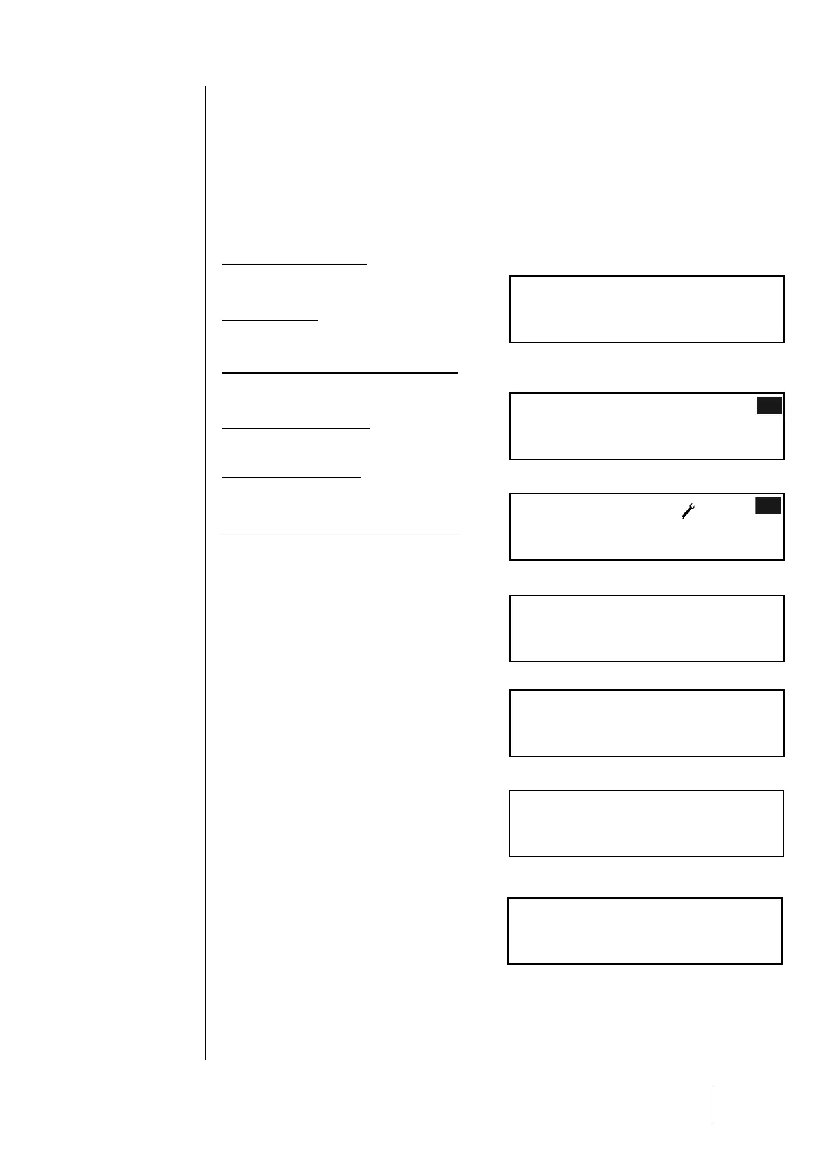
Module 2, line 8 turned on
30/06/06 (day/month/year) 14:40:36 L:8, Mod:02
Module ON
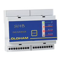
Alarm 2 triggered
30/06/06 14:49:37 L:8, Mod:02
Alarm 2, OFF ON
State change for Relay 2 (command relay)
30/06/06 14:49:37 L:8, Mod:29
Relay 2 Normal ON
Conditions for Alarm 2 end
30/06/06 14:51:03 L:8, Mod:02
Alarm 2, ON OFF
Acknowledgement action
30/06/06 14:55:21
ACKNOWL
State change for Relay 2 (relay shut-down)
30/06/06 14:55:21 L:8, Mod:29
Relay 2 Normal OFF
Relay Status
This menu displays the status of a relay in a given
module. Increments for the preceding and
following modules in the line are automatically
calculated.
Display the status for the selected relay by
pressing the [OK] button. This screen will show the
module, its mode of operation (Normal, Buzzer,
LS, HS,...) and its status (ON, OFF).
(a): (LS / HS) - Delays
(a): (Buzzer Relay) – Acknowledgement time
(b): (Buzzer Relay) – Min. activation
4-20 mA Output Status
This menu displays the outputs for the selected
module. The value is displayed in mA.
Multiple inputs can be linked to one output. In this
case, the largest analog value will be recopied
onto the analog output.
Activated analog output: the 4-20 mA output signal varies according to the input.
Deactivated analog output: the 4-20 mA output signal will be frozen at 0mA, regardless of the input
signal. The output current for each channel will vary between 0 and 24.5 mA.
kkkkkkk