Manual calibration
The calibration kit provided by ISC must be used (Ref. 6 116 291) female connector / wires /
voltmeter connection files).
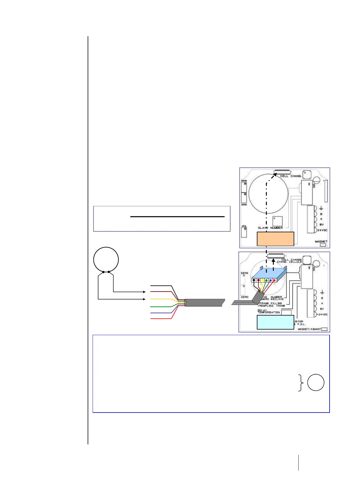
- Remove the sensor cover.
- Connect the cable (strand) to the circuit’s male connector.
Zero adjustment
Ensure that the sensor is in clean air. If not, inject air into the sensor at a flow rate of 60 l/h, then
wait for voltmeter levels to stabilize (use the gas injection device: bottle of synthetic air, calibration
pipe, tube).
- Adjust the zero with the potentiometer’s “ZERO” until the voltmeter reads 0 mV.
Sensitivity adjustments
- Now inject the known gas (60 l/h) into the sensor, and wait for the voltmeter signal to stabilize.
- Adjust the sensitivity if necessary with the potentiometer “SENS” until the signal value (in mV)
corresponds to the amount of reference gas used. Use the following formula to calculate
the correct value for the signal.
- Stop injecting gas (remove the calibration pipe from the sensor).
- Wait for the voltmeter to “return to zero.”
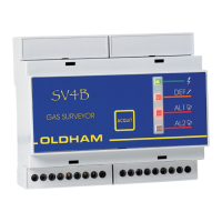
Version CPS 10 for explosive gas
The CPS central controller has a “verification” function: if
the sensor measures a concentration of gas higher than
100% LEL, the signal will be dismissed by disconnecting its
power supply.
MAINTENANCE WIRES:
+VCC ( red ) = + power supply
Signal S ( yellow ) = signal from 0 mV to 1600 mV for zero and sensitivity measure
Ref 2,5V ( brown) = zero reference for signal reading from 0 mV to1600 mV
GND ( black ) = electronic circuit ground.