EasyManuals Logo

Oldham CPS Series User Manual

Oldham CPS Series
76 pages
To Next Page IconTo Next Page
To Previous Page IconTo Previous Page
Page #19 background imageLoading...
Page #19 background image
CPS User Manual
Page 19
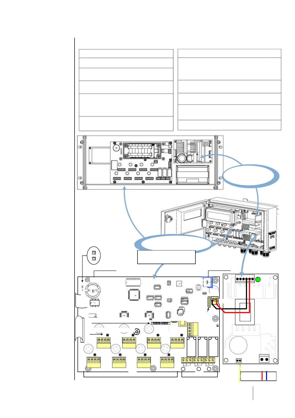
Overview of the Motherboard
The wall-mounted version connects directly to the power supply board.
Part
Connector function
(1)
110-240VCA main power supply (rack
version)
(2)
24 VDC external power supply connection
(3)
110-240VCA power supply for (wall-
mount) power supply module
(4)
24 VDC power supply output for power
supply module
motherboard + integrated printer (rack-
version option) power
(5)
Internal contact relay outputs (RTC)
dry contacts, potential free
Part
Connector function
(6)
Digital addressable modules
8 line connectors for connecting digital modules
(CPS 10 CPSRM CPSDI16 CPSAO4)
(7)
RS-485 digital output
links to a supervision system
(8)
USB serial interface
(PC/COM_CPS connection for configuration)
(9)
RS-232 serial interface link
PC/COM_CPS connection for configuration,
External serial printer connection
R1, R2, R3
: central station shared internal relays
+Def
J23
J24
J25
Front plate
plate
R3
R2
R1
N
L
1
2
3
B
J10
Bus 1
Bus 3
Bus 5
Bus 7
Bus 2
Bus 4
Bus 6
Bus 8
Communication DEL
Power supply (option)
(7)
( 8 )
(9)
(2)
( 4 )
Strap activation
buzzer
Buzzer
Memory
Lithium battery
(6)
(5)
( 3 )
Motherboard
Power supply
board
N
L
PE
0V +Vcc
+Vcc
110-240VCA
(1)
Display
board
Configuration switch
Wall mounted CPS

Table of Contents

Questions and Answers:

Question and Answer IconNeed help?

Do you have a question about the Oldham CPS Series and is the answer not in the manual?

Oldham CPS Series Specifications

General IconGeneral
BrandOldham
ModelCPS Series
CategoryGas Detectors
LanguageEnglish

Related product manuals