2KR/2KS
1-5-23
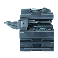
6. Remove two screws and two connectors,
and then remove the fan duct.
Figure 1-5-46
7. Remove six screws and remove the toner
container retainer.
Figure 1-5-47
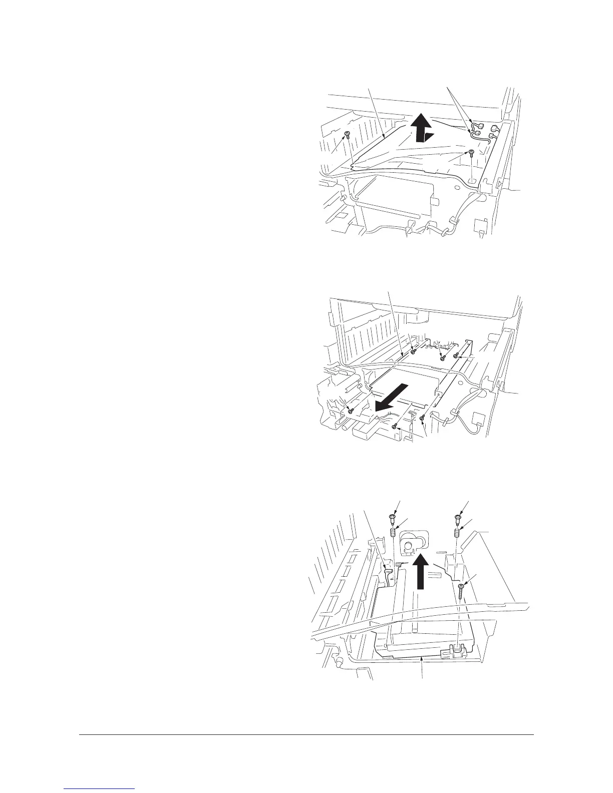
8. Remove two pins, two springs, one screw
and one connector.
9. Remove the laser scanner unit.
10. Replace the laser scanner unit and install
the unit.
11. Refit the toner container retainer, fan duct
and inner cover.
12. Refit the top tray, front right cover, right
lower cover and front left cover.
13. Refit the drum unit and the developing unit.
Figure 1-5-48
Fan duct
Connectors
Screw
Screw
Toner container retainer
Screw
Screws
Screw
Screw
Screw
Pin
Spring
Pin
Spring
Screw
Connector
Laser scanner unit
Y111960-2 Service Manual

 Loading...