DMTA041-01EN [U8778479], Rev. C, May 2014
Chapter 6
60
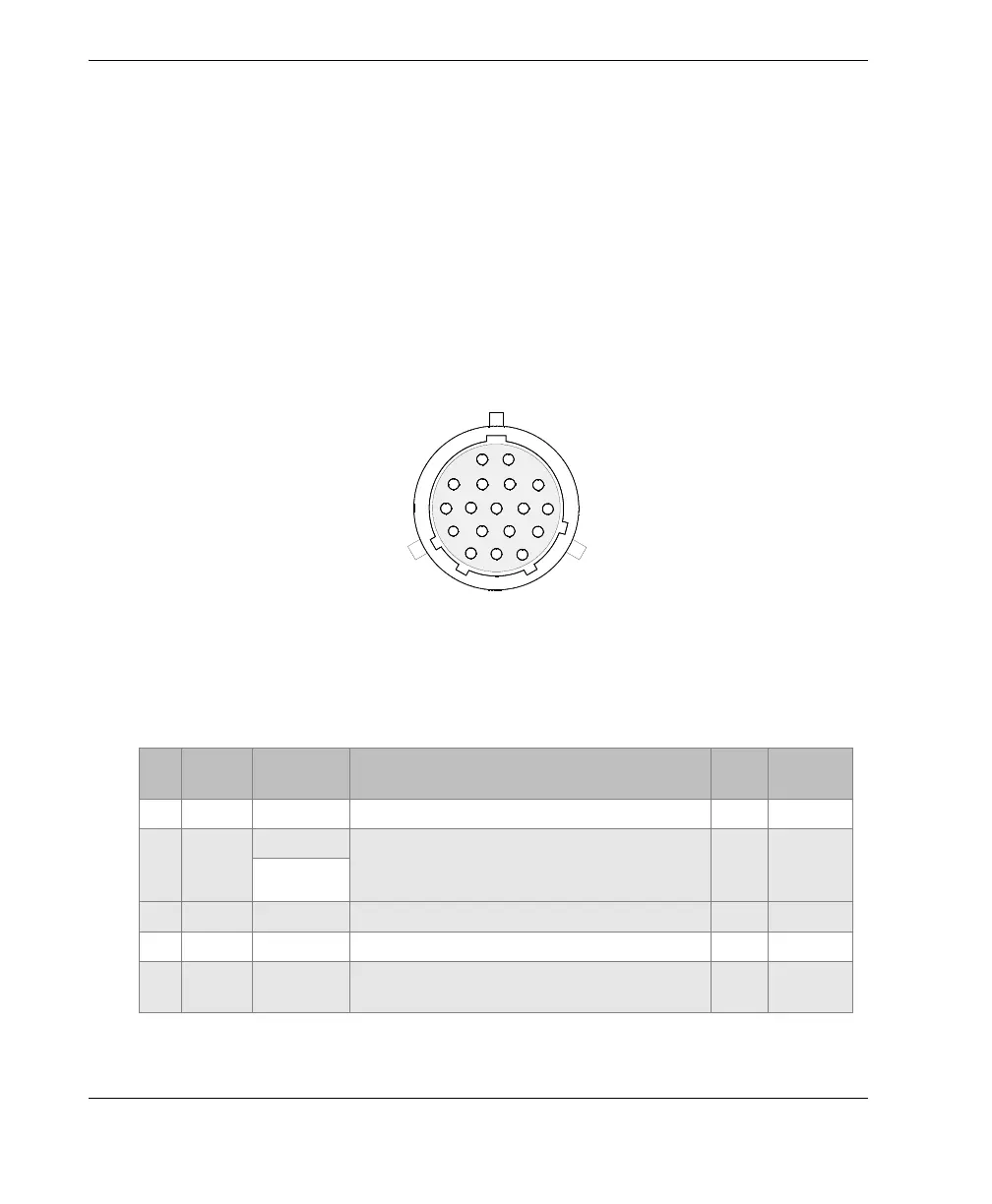
6.1 I/O Connector
Description
18-pin, female, shell 14
Manufacturer; number
ITT Cannon; KPT02A14-18S
Olympus; 21AN0005 [U8902976]
Suggested cable connector; number
ITT Cannon; KPT06B14-18P
Olympus; 21AN0011 [U88780063]
Figure 6-1 The
I/O connector
Table 13 Pinout for the
I/O connector
Pin I/O Signal Description Type
Signal
length
A Input PhB-1 Encoder 1: phase B / direction
TTL
a
B Output Dout1 Programmable output. Configured as
PaceOut (external pace signal) in the
TomoView software.
TTL
a.
1µs
Pace Out
C Input PhA-2 Encoder 2: phase A / Clock / Up / Down
TTL
a.
D— GNDGround —
E Output AL2 Alarm output 2. Disabled on reset, value:
0 V. When active, value: 5 V.
TTL
a.