DMTA041-01EN [U8778479], Rev. C, May 2014
Connector References
61
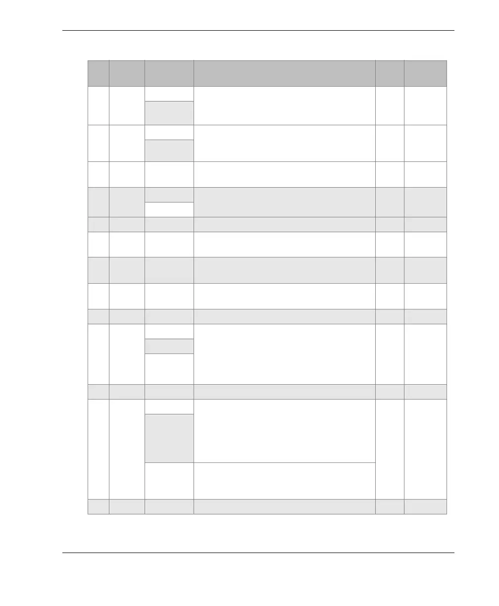
F Input Din1 Programmable input.
Can be configured as preset encoder 1 from
TomoView software.
TTL
a.
>= 50 µs
Preset1
G Input Din3 Programmable input. Can be configured as
pause acquisition from the TomoView
software.
TTL
a.
As long
as pause
time
AcqEn
H Output AL1 Alarm output 1. Disabled on reset, value:
0 V. When active, value: 5 V.
TTL
a.
J Output Dout2 Programmable output. Can be set as TrigOut
from the TomoView software.
TTL
a.
160 ns
TrigOut
K — GND Ground —
L Output Dout3 Programmable output. Not programmed in
TomoView.
TTL
a.
M Output AL3 Alarm output 3. Disabled on reset, value:
0 V. When active, value: 5 V.
TTL
a.
N Output Dout4 Programmable output. Not programmed in
TomoView.
TTL
a.
P Input PhB-2 Encoder 2: phase B / direction
TTL
a.
R Input Din2 Programmable input.
Can be configured as rotation sync input
(revolution synchronization signal)
or as preset of encoder 2 from the TomoView
software.
TTL
a.
Preset:
>= 50 µs /
rotation
sync
input
Rev. Sync.
Preset2
S Output +5 V Supply output voltage, 500 mA max. — —
T Input Din4
Programmable input. Can be
configured as either ExtPace (external
pace or trigger)
or Start/Stop acquisition from the
TomoView software.
TTL
a.
External
firing:
>= 50 µs
ExtPace
Start/Stop
acquisition
Start/Stop acquisition from the TomoView
software. High: start acquisition. Low: Stop
acquisition
U Input PhA-1 Encoder 1: phase A / Clock / Up / Down
TTL
a.
a. For all TTL types, there is a tolerance of 0.5 V so voltage plateau can vary between 4.5 V
and 5.5 V.
Table 13 Pinout for the I/O connector (continued)
Pin I/O Signal Description Type
Signal
length