9
2.5 Network Communication Interfaces
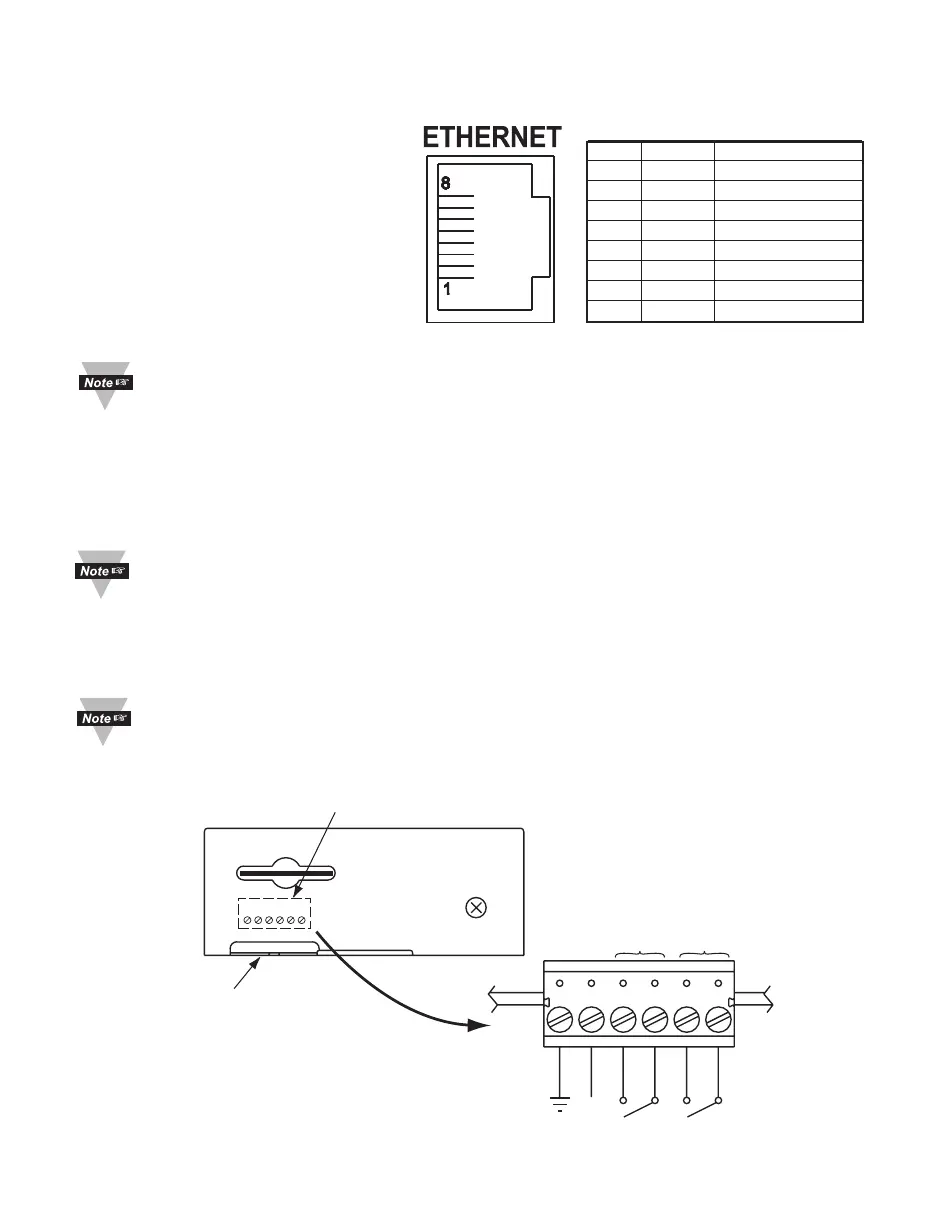
2.5.1 10/100 BASE-T RJ-45 Pinout
The 10/100BASE-T Ethernet network
system is used in the iServer for
network connectivity. The 10 Mbps
or 100 Mbps twisted-pair Ethernet
system operates over two pairs of
wires. One pair is used for receiving
data signals and the other pair is used
for transmitting data signals. This
means that four pins of the eight-pin
connector are used.
For CE compliance at 100
Mbps: use shielded cable,
opposite end of cable must be grounded.
2.5.2 Connecting iServer to PC/Hub/Switch/Router
The iServer’s Ethernet interface can automatically detect the Rx and Tx lines on a
twisted pair Ethernet cable (MDI/MDIX Auto Cross). Therefore, to connect an iServer to a
PC/Hub/Switch/Router, either a straight-through or a cross-over cable can be used.
On certain devices (like iServer), it is possible for the hardware to automatically
correct errors in cable selection, making the distinction between a “straight-
through” cable and a “cross-over” cable unimportant. This capability is known as
“Auto MDI/MDIX”.
2.6 Relay Wiring Connections
To access the Relay Connector you must remove the cover, refer to Section 2.4.
It is recommended that you ground your unit by connecting a wire to the
Ground/Return position of the relay connector.
6234
NO1
NO2
9 Vdc
RTN
COM2
COM1
RELAY 2 RELAY 1
Side or Bottom
Wire Entry for
Relay Connector
Connector for Relays
under the Cover
6
1
Figure 2.6 Relay Connections
Pin Name Description
1 +Tx +Transmit Data
2 - Tx -Transmit Data
3 +RX +Receive Data
4 N/C Not Connected
5 N/C Not Connected
6 -Rx -Receive Data
7 N/C Not Connected
8 N/C Not Connected
Figure 2.5 RJ45 Pinout