CP TD1 Reference Manual V 1.44
102
This connection technique is also very useful when the insulation of cables is
measured.
When transformer bushings are tested, inputs A and B can be used to measure
two bushings at a time without rewiring:
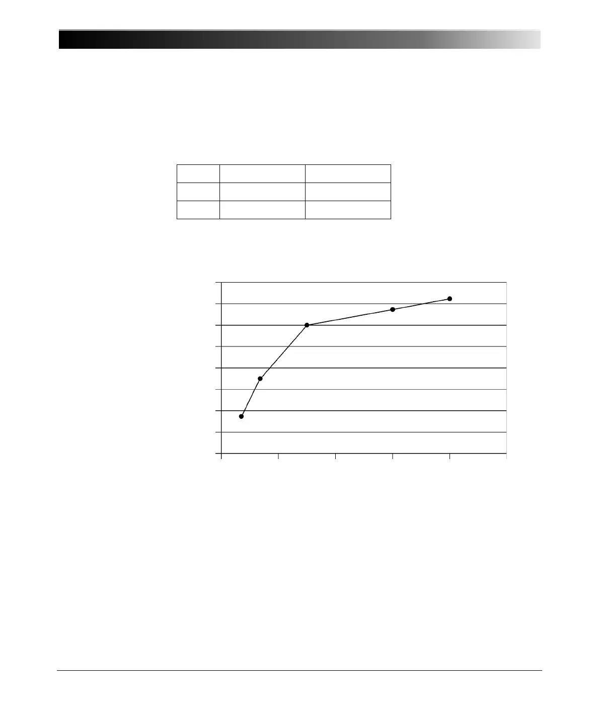
Frequency scans of bushing insulation are helpful for a better diagnosis. Figure
7-8 shows a frequency scan of a new RIP bushing, Figure 7-9 of an aged one.
This additional information should be used as benchmark of the bushing for
future comparison.
Figure 7-8 Frequency scan of a new RIP bushing
Test UST A (IN A) UST B (IN B)
1 Phase A Phase B
2 Phase C Neutral
0.33%
0.32%
0.31%
0.30%
0.29%
0.28%
0.27%
0.26%
0.25%
0.0Hz 100Hz 200Hz 300Hz 400Hz 500Hz

 Loading...


