EasyManua.ls Logo

Omicron CP TD1 - Page 36

Omicron CP TD1
70 pages
To Next Page IconTo Next Page
To Previous Page IconTo Previous Page
Loading...
CP TD1 User Manual
36 OMICRON
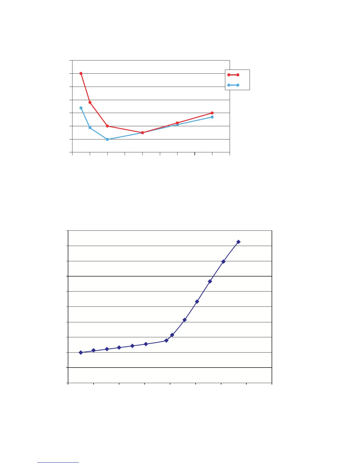
Figure 4-9: Frequency dependent dissipation factor of two OIP bushings (phase A and phase B
If the dissipation factor is also dependent on the voltage, this is an indication for partial discharges or
contact problems. Figure 4-10 shows a measurement of a 6kV motor. Above 4kV, partial discharges
occur which increase the dissipation factor.
Figure 4-10: Voltage dependent dissipation factor of a 6 kV motor
0.67 %
0.0 Hz
0.66 %
0.65 %
0.64 %
0.63 %
0.62 %
0.61 %
0.60 %
50.0 Hz
100.0 Hz
150.0 Hz
200.0 Hz
250.0 Hz
300.0 Hz
350.0 Hz
400.0 Hz
450.0 Hz
A
B
1.6 %
1.5 %
1.4 %
1.3 %
1.2 %
1.1 %
1.0 %
0.9 %
0.8 %
0.7 %
0.6 %
0 V 1 kV 2 kV 3 kV 4 kV 5 kV 6 kV 7 kV 8 kV

Table of Contents

Other manuals for Omicron CP TD1

Related product manuals