CP TD1 User Manual
42 OMICRON
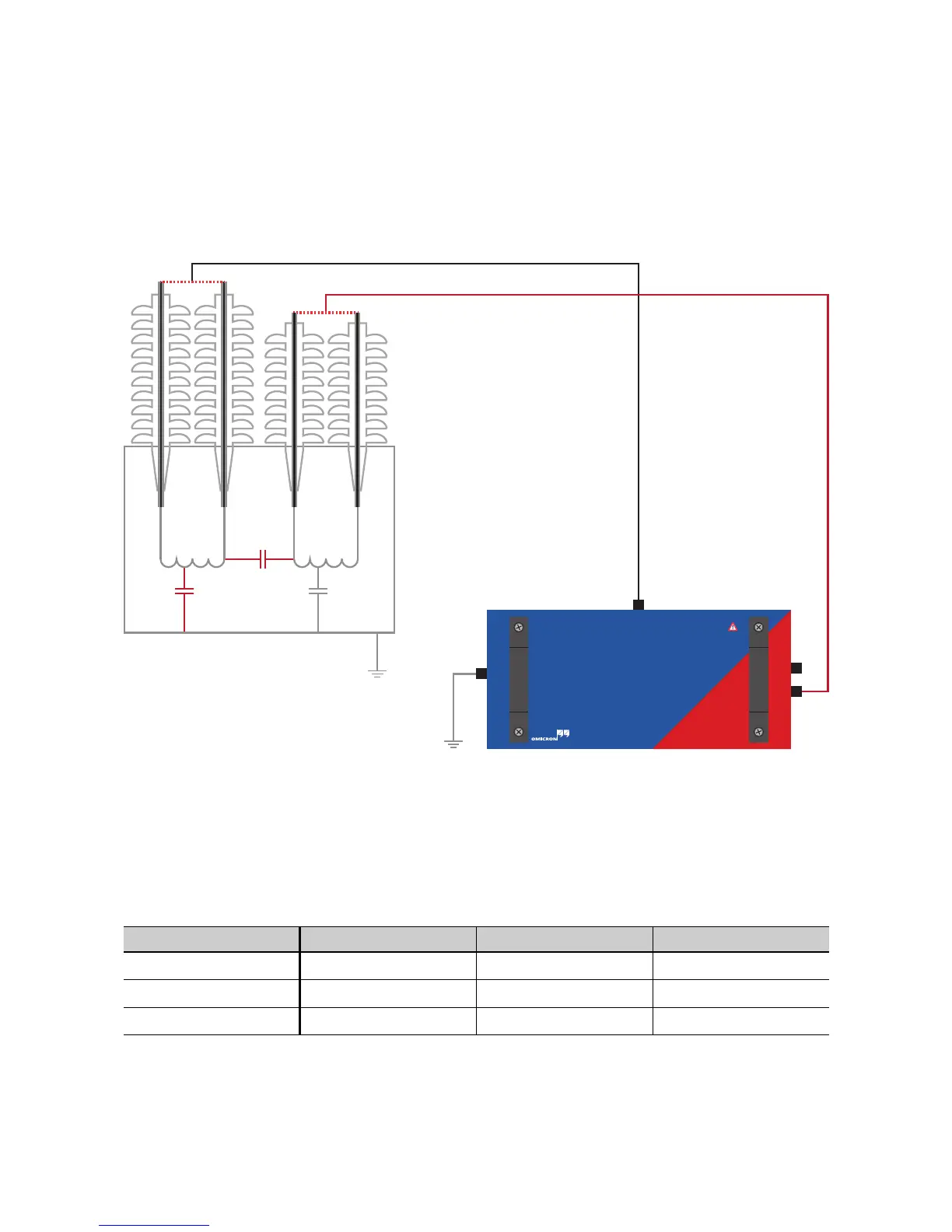
Dielectric measurements on a two-winding power transformer usually include all 3 insulations C
HL
, C
H
and C
L
. To measure C
HL
and C
H
, the HV output of the CP TD1 is connected to the HV side and IN A to
the LV side (see Figure 5-3 on page 42). To prevent induced currents, all bushings of the HV side are
shortened, the same applies to the LV side. The ground of the transformer and the ground of the CP TD1
are connected.
Figure 5-3: CP TD1 connected to a two-winding transformer for the measurement of C
HL
and C
H
With this setup 3 configurations are available (see Table 5-1 below). C
HL
and C
H
can be measured
without reconnecting.
IN B is not connected, so the modes GSTg-A and GSTg-(A+B) give the same result as it makes no
difference whether the current over IN B is guarded or measured.
Table 5-1: Modes available with a measurement setup as seen in Figure 5-3
Mode IN A Ground Result
UST-A Measured Guarded C
HL
GSTg-A or GSTg-(A+B) Guarded Measured C
H
GSTg-B Measured Measured C
HL
+ C
H

 Loading...


