Conventional Vehicle Types Installation Planning
4-8 80-JB400-1 Rev. D
MAY CONTAIN U.S. AND INTERNATIONAL EXPORT CONTROLLED INFORMATION
- J1939: main fuse panel, top of dash 2 pin Deutsch connector between the fuse panel
and the windshield. Yellow (+) and Green(-) wires
- TTRACS: driver side firewall, or floorboard behind driver seat, connect to wire labeled
“AUX”
Peterbilt 378/379
• MAS110—Install on side wall or under the bunk.
- Install so there is access to a USB port for the
memory stick and access to backup battery.
•DIU110—Install on dash where space allows/customer
preference.
• Cables—Route display cables internally or externally.
- Connect power cable to solenoid behind
pyrometer panel.
- Cables exit/enter the sleeper floor near MAS110.
- Cables enter/exit cab through firewall, high on passenger side. Use existing cable path.
Remove map box.
- Drill a 1" hole in floor of side box for antenna cable.
• Typical Connection Points
- Chassis ground: main frame just below the solenoid
- Ignition: ignition switch or solenoid mounted behind speedometer
- J1708: dash, behind speedometer/tach. Purple (+) and White (-) wires
Post March 2005 trucks - Purple (+) and Green (-)
- J1939: behind A pillar or ignition switch, Blue AMP connection
- TTRACS: behind driver side fuse panel, Black wire labeled AUX
Peterbilt 387
• MAS110—Hang under the bunk.
- Install so there is access to a USB port for the
memory stick and access to backup battery.
•DIU110—Install on dash where space allows/customer
preference.
• Cables—Route externally.
- Drill a 1" hole in floor of side box for antenna cable.
• Typical Connection Points
- Power: passenger side main fuse panel, behind glove box, 3rd row open fuses
- Chassis ground: passenger side main fuse panel - belting support bracket
- Ignition: passenger side main fuse panel, behind glove box, 2rd row open fuses
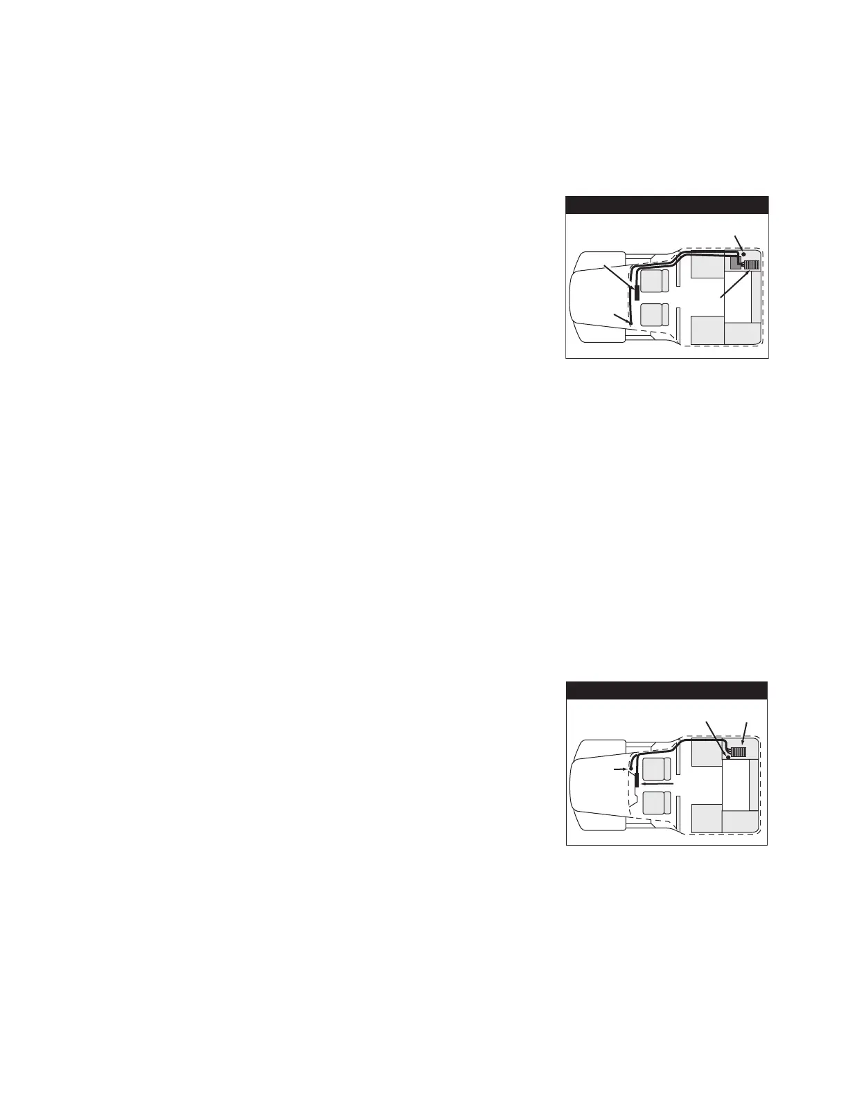
Peterbilt
Display
Power-
solenoid
behind
pyrometer
panel
MAS
Antenna cable
access hole
Existing
heater
box
Display
Power-
Main
Power Bus
Antenna cable
access hole
MAS
Peterbilt
 Loading...