Making the Connection Vehicle Data Bus Connections
9-6 80-JB400-1 Rev. D
MAY CONTAIN U.S. AND INTERNATIONAL EXPORT CONTROLLED INFORMATION
4. Locate the J1939 bus wires.
• The J1939 wires are a twisted pair
• CAN high (J1939+) (yellow)
• CAN low (J1939-) (green)
5. Determine a suitable J1939 location point. In many vehicles you can connect behind the
truck diagnostic connector. Be aware that only one electronic device should be
connected to the J1939 stub at the back of the diagnostic connector at a time. If another
device is already present you will need to splice directly into the vehicle’s J1939
backbone. When splicing directly to the J1939 backbone bus, you will need to Ohm out
(0 Ohms) CAN + and CAN - wires to Pin C (CAN high) and Pin D (CAN low) on the
diagnostic connector. Contact Omnitracs Customer Support for assistance if needed.
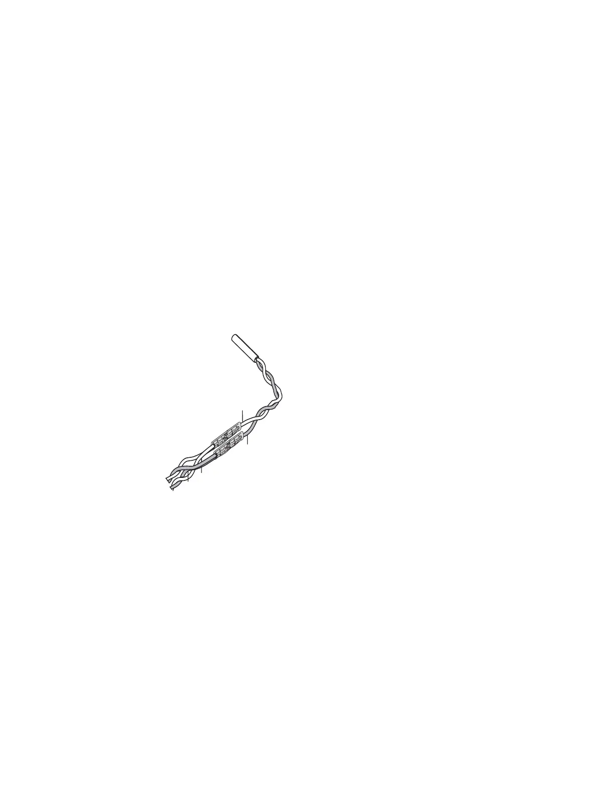
6. Splice the yellow CAN high J1939+ wire from the repeater cable to the yellow CAN high
J1939+ wire from the truck’s J1939 bus. (Refer to the illustration on page 9-5.)
7. Splice the green CAN low J1939- wire from the repeater cable to the green CAN low
J1939- wire from the truck’s J1939 bus. (Refer to the illustration on page 9-5.)
8. Measure the J1939 bus resistance from Pin C to Pin D at the diagnostic connector. It
should read 60 ohms.
9. Locate the CAN 6-pin Molex connector on the MCP110 accessory cable.
J1939+
Yellow
J1939-
Green
J1939+
J1939-
08AAA_048B
J1939
Converter cable
Truck's
J1939 bus