The register settings here are different from the definitions descried in the Power PMAC Software
Reference Manual (Cat. No. O015).
Refer to A-9 Software Reference of Laser Interface Unit on page A-33 for detailed specifications.
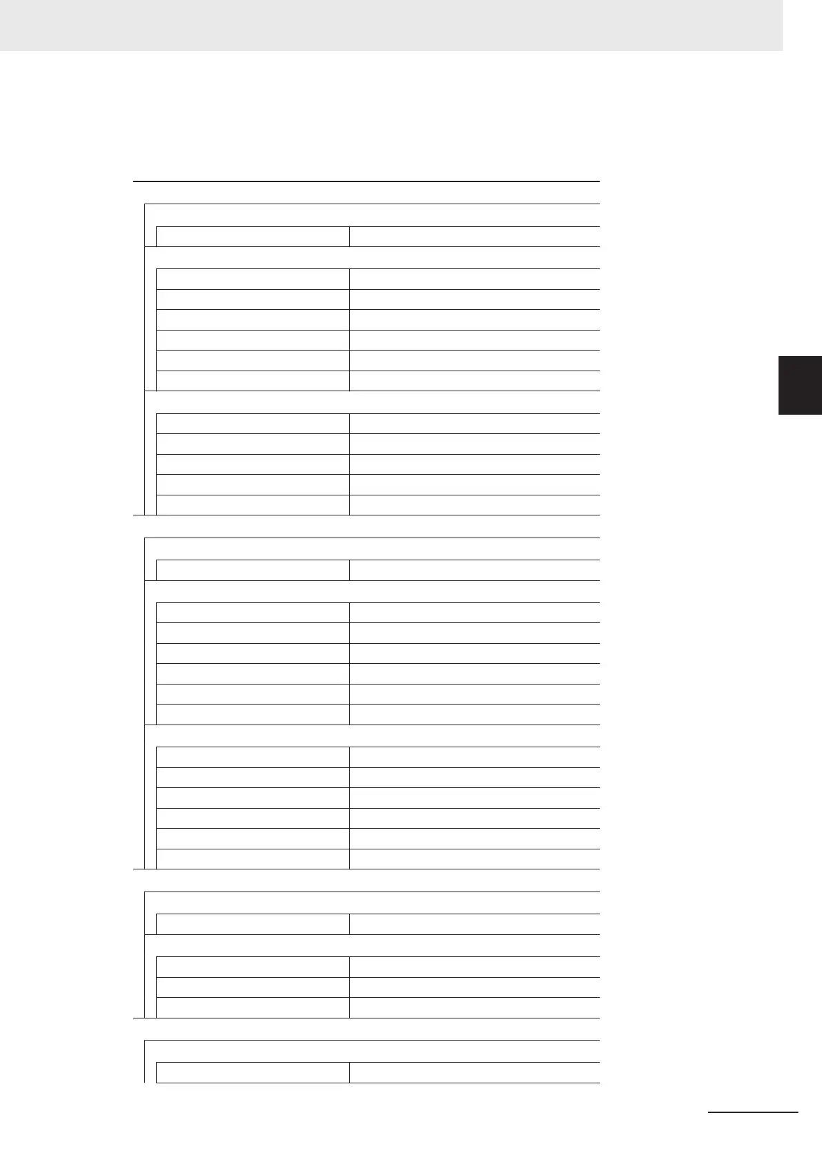
XY2-100 Interface
Power PMAC Saved Data Structure Elements
Gate3[i].SerialEncCtrl Control register
Power PMAC Non-Saved Data Structure Elements
Gate3[i].Chan[0].Dac[0] X-axis command position
Gate3[i].Chan[1].Dac[0] Y
-axis command position
Gate3[i].Chan[2].Dac[0] Z-axis command position
Gate3[i].Chan[0].Dac[1] X-axis compensation value
Gate3[i].Chan[1].Dac[1] Y-axis compensation value
Gate3[i].Chan[2].Dac[1] Z-axis compensation value
Power PMAC Status Data Structure Elements
Gate3[i].Chan[0].SerialEncDataA X-axis command position after interpolation
Gate3[i].Chan[1].SerialEncDataA Y-axis command position after interpolation
Gate3[i].Chan[2].SerialEncDataA Z-axis command position after interpolation
Gate3[i].Chan[0].SerialEncDataB XY-axis status
Gate3[i].Chan[2].SerialEncDataB Z-axis status
SL2-100 Interface
Power PMAC Saved Data Structure Elements
Gate3[i].SerialEncCtrl Control register
Power PMAC Non-Saved Data Structure Elements
Gate3[i].Chan[0].Dac[0] X-axis command position
Gate3[i].Chan[1].Dac[0] Y-axis command position
Gate3[i].Chan[2].Dac[0] Z-axis command position
Gate3[i].Chan[0].Dac[1] X-axis compensation value
Gate3[i].Chan[1].Dac[1] Y-axis compensation value
Gate3[i].Chan[2].Dac[1] Z-axis compensation value
Power PMAC Status Data Structure Elements
Gate3[i].Chan[0].SerialEncDataA X-axis reception data
Gate3[i].Chan[1].SerialEncDataA Y-axis reception data
Gate3[i].Chan[2].SerialEncDataA Z-axis reception data
Gate3[i].Chan[0].SerialEncDataB X-axis status
Gate3[i].Chan[1].SerialEncDataB Y-axis status
Gate3[i].Chan[2].SerialEncDataB Z-axis status
PWM output
Power PMAC Saved Data Structure Elements
Gate3[i].SerialEncCtrl Control register
Power PMAC Non-Saved Data Structure Elements
Gate3[i].Chan[0].CompA PWM setting
Gate3[i].Chan[1].CompA Delay setting
Gate3[i].Chan[2].CompA Pulse count
TCR output
Power PMAC Non-Saved Data Structure Elements
Gate3[i].Chan[0].CompB Command distance
3 Configuration Units
3-85
CK3M-series Programmable Multi-Axis Controller User's Manual Hardware (O036)
3-7 Laser Interface Unit
3
3-7-10 Software Settings

 Loading...


