86
Operating Procedure Section 3-2
Initial Data Settings
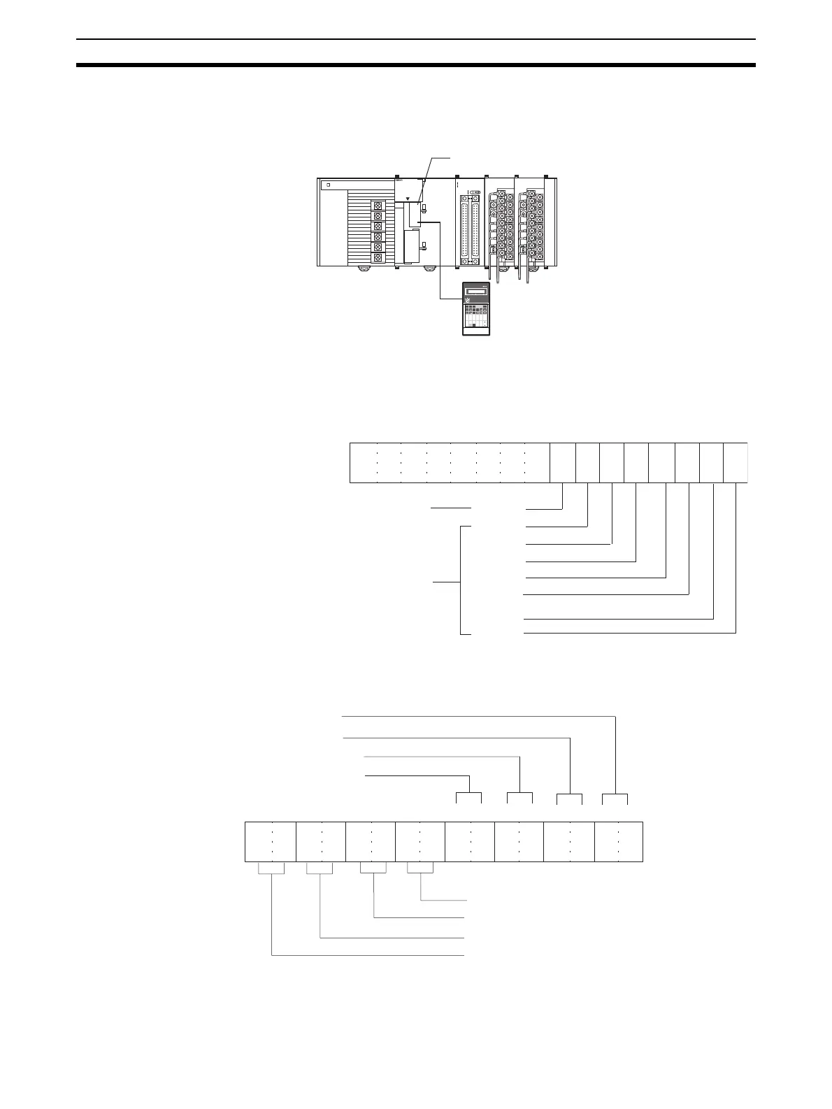
1,2,3... 1. Specify the Special I/O Unit DM Area settings. Refer to 3-5-4 Fixed Data
Allocations for further details.
• The following diagram shows the input settings used. Refer to DM Al-
location Contents on page 99 and 3-6-1 Input Settings and Conversion
Values for more details.
• The following diagram shows the input range settings. Refer to DM Al-
location Contents on page 99 and 3-6-1 Input Settings and Conversion
Values for more details.
OD261
SYSMAC
CJ1G-CPU44
PROGRAMMABLE
CONTROLLER
RUN
ERR/ALM
INH
PRPHL
COMM
OPEN
PERIHERAL
PORT
MCPWR
BUSY
01234567
8 9 10 11 12 13 14 15
20
1
CN1
DC24V 0.3A
1
20
CN2
B/A A
/B
0
1
2
3
01234567
8 9 10 11 12 13 14
15
AD081
B1 A1
MACH
No.
x10
1
x10
0
RUN
ERC
ERH
ADJ
MODE
12
DA041
B1 A1
MACH
No.
x10
1
x10
0
RUN
ERC
ERH
ADJ
MODE
12
Analog input 1: 1 to 5 V
Analog input 2: 1 to 5 V
Analog input 3: 4 to 20 mA
Analog input 4: 4 to 20 mA
Analog input 5: 0 to 10 V
Analog input 6: 0 to 10 V
Analog input 7:
−10 to 10 V
Analog input 8: Not used.
Programming Console
Peripheral port
15 14 13 12 11 10 09 08 07 06 05 01 0004 03 02
0 0 0 0 0 0 0 0 0 1 1 1 1 1 1 1
Bit
Input 4
Input 3
Input 2
Input 1
Used
m: D20100
(007F Hex)
Not used
Input 8
Input 7
Input 6
Input 5
15 14 13 12 11 10 09 08 07 06 05 01 0004 03 02
0 0 0 0 0 1 0 1 0 0 1 0 1 0 1 0
Bit
m+1: D20101
(05AA Hex)
Input 1: 1 to 5 V. Set to 10.
Input 2: 1 to 5 V. Set to 10.
Input 3: 4 to 20 mA. Set to 10.
Input 4: 4 to 20 mA. Set to 10.
Input 5: 0 to 10 V. Set to 01.
Input 6: 0 to 10 V. Set to 01.
Input 7: −10 to 10 V. Set to 00.
Input 8: Not used. Set to 00 (disabled).
 Loading...


