87
Operating Procedure Section 3-2
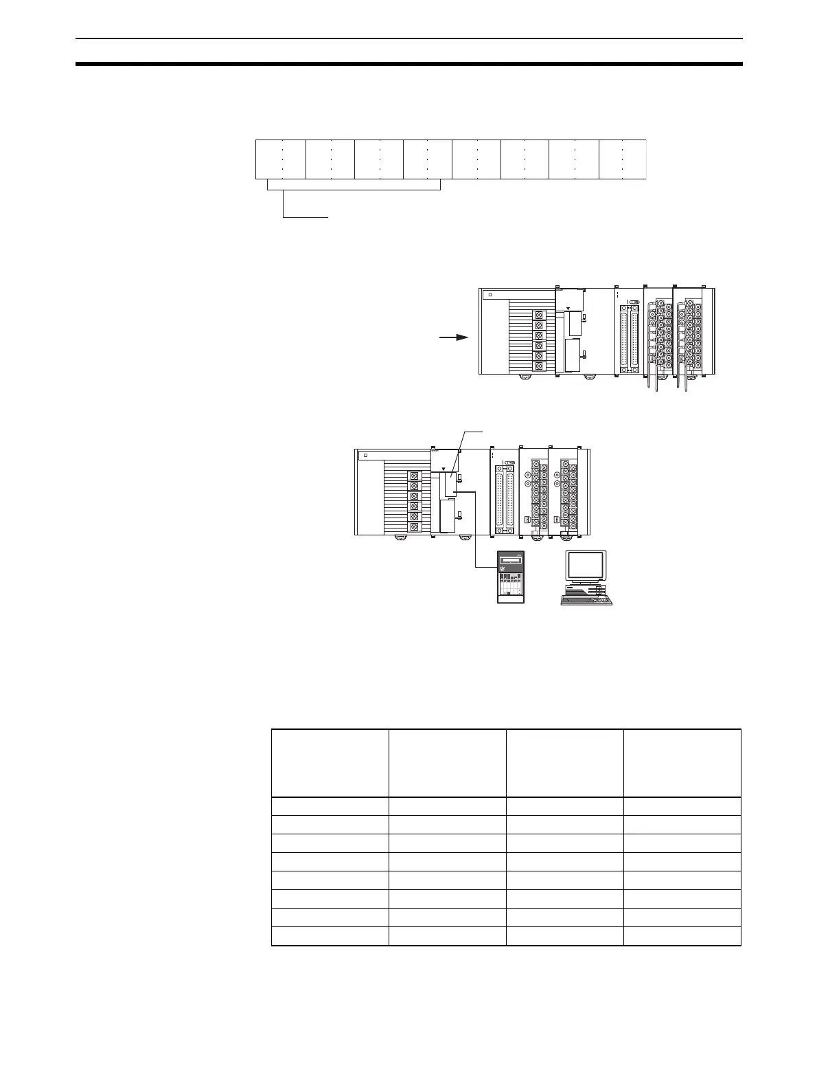
• The following diagram shows the conversion time/resolution setting.
(Refer to
3-6-2 Conversion Time/Resolution Setting.)
2. Restart the CPU Unit.
Creating Ladder Programs
The data that is converted from analog to digital and output to CIO words (n +
1) to (n+ 7) of the Special I/O Unit Area (CIO 2011 to CIO2017), is stored in
the specified addresses D00100 to D00106 as signed binary values 0000 to
0FA0 Hex.
• The following table shows the addresses used for analog input.
Note 1. The addresses are fixed according to the unit number of the Special I/O
Unit. Refer to 3-3-2 Unit Number Switch for further details.
15 14 13 12 11 10 09 08 07 06 05 01 0004 03 02
0 0 0 0 0 0 0 0
Bit
m+18: D20118
(0000 Hex)
Conversion Time/Resolution Setting
0000: 1-ms conversion time, 4,000 resolution
C100: 250-
µs conversion time, 8,000 resolution
OD261
SYSMAC
CJ1G-CPU44
PROGRAMMABLE
CONTROLLER
RUN
ERR/ALM
INH
PRPHL
COMM
OPEN
PERIHERAL
PORT
MCPWR
BUSY
01234567
8 9 10 11 12 13 14 15
20
1
CN1
DC24V 0.3A
1
20
CN2
B/A A
/B
0
1
2
3
01234567
8 9 10 11 12 13 14
15
AD081
B1 A1
MACH
No.
x10
1
x10
0
RUN
ERC
ERH
ADJ
MODE
12
DA041
B1 A1
MACH
No.
x10
1
x10
0
RUN
ERC
ERH
ADJ
MODE
12
Power turned ON again
(or Special I/O Unit Restart
Bit is turned ON).
Input number Input signal range Input conversion
value address
(n = CIO 2010)
(See note 1.)
Conversion data
holding address
(See note 2.)
1 1 to 5 V (n+1) = CIO 2011 D00100
2 1 to 5 V (n+2) = CIO 2012 D00101
3 4 to 20 mA (n+3) = CIO 2013 D00102
4 4 to 20 mA (n+4) = CIO 2014 D00103
5 0 to 10 V (n+5) = CIO2015 D00104
6 0 to 10 V (n+6) = CIO2016 D00105
7 –10 to 10 V (n+7) = CIO2017 D00106
8 Not used --- ---
OD261
SYSMAC
CJ1G-CPU44
PROGRAMMABLE
CONTROLLER
RUN
ERR/ALM
INH
PRPHL
COMM
OPEN
PERIHERAL
PORT
MCPWR
BUSY
01234567
8 9 10 11 12 13 14 15
20
1
CN1
DC24V 0.3A
1
20
CN2
B/A A
/B
0
1
2
3
01234567
8 9 10 11 12 13 14
15
AD081
B1 A1
MACH
No.
x10
1
x10
0
RUN
ERC
ERH
ADJ
MODE
12
DA041
B1 A1
MACH
No.
x10
1
x10
0
RUN
ERC
ERH
ADJ
MODE
12
Peripheral port
Programming Console
OR
Personal computer
 Loading...


