102
Exchanging Data with the CPU Unit Section 3-5
2. If two or more Special I/O Units are assigned the same unit number, a
“UNIT No. DPL ERR” error (in the Programming Console) will be generat-
ed (A40113 will turn ON) and the PLC will not operate.
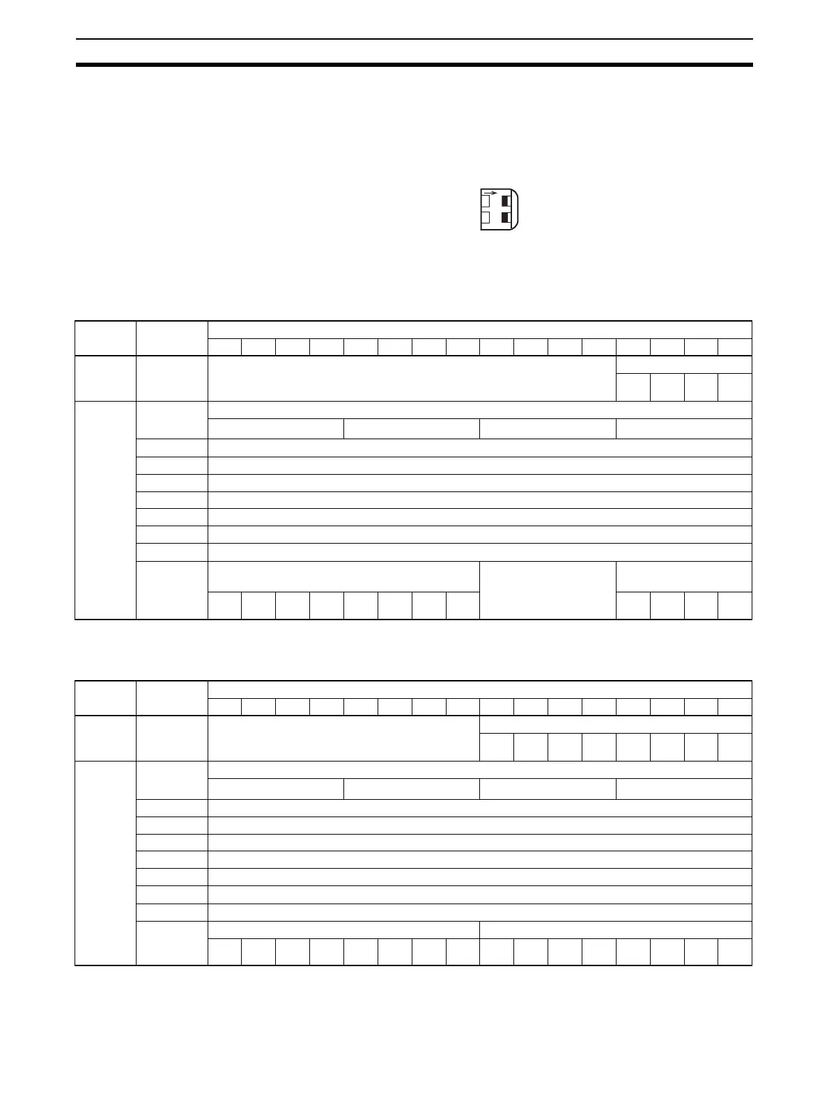
Allocations for Normal
Mode
For normal mode, set the operation mode switch on the front panel of the Unit
as shown in the following diagram, or set bits 00 to 07 in DM word m+18.
The allocation of words and bits in the CIO Area is shown in the following
table.
CJ1W-AD041-V1
Note For the CIO word addresses, n = CIO 2000 + (unit number x 10).
CJ1W-AD081-V1
Note For the CIO word addresses, n = CIO 2000 + (unit number x 10).
O
N
12
MODE
OFF
OFF
I/O Word Bits
1514131211109876543210
Output
(CPU to
Unit)
n Not used. Peak value hold
Input
4
Input
3
Input
2
Input
1
Input
(Unit to
CPU)
n + 1 Input 1 conversion value
16
3
16
2
16
1
16
0
n + 2 Input 2 conversion value
n + 3 Input 3 conversion value
n + 4 Input 4 conversion value
n + 5 Not used.
n + 6 Not used.
n + 7 Not used.
n + 8 Not used.
n + 9 Alarm Flags Not used. Disconnection detec-
tion
Input
4
Input
3
Input
2
Input
1
I/O Word Bits
1514131211109876543210
Output
(CPU to
Unit)
n Not used. Peak value hold
Input
8
Input
7
Input
6
Input
5
Input
4
Input
3
Input
2
Input
1
Input
(Unit to
CPU)
n + 1 Input 1 conversion value
16
3
16
2
16
1
16
0
n + 2 Input 2 conversion value
n + 3 Input 3 conversion value
n + 4 Input 4 conversion value
n + 5 Input 5 conversion value
n + 6 Input 6 conversion value
n + 7 Input 7 conversion value
n + 8 Input 8 conversion value
n + 9 Alarm Flags Disconnection detection
Input
8
Input
7
Input
6
Input
5
Input
4
Input
3
Input
2
Input
1
 Loading...


