103
Exchanging Data with the CPU Unit Section 3-5
Set Values and Stored Values
Note For the CIO word addresses, n = CIO 2000 + unit number x 10.
The input disconnection detection function can be used when the input signal
range is set for 1 to 5 V (4 to 20 mA).
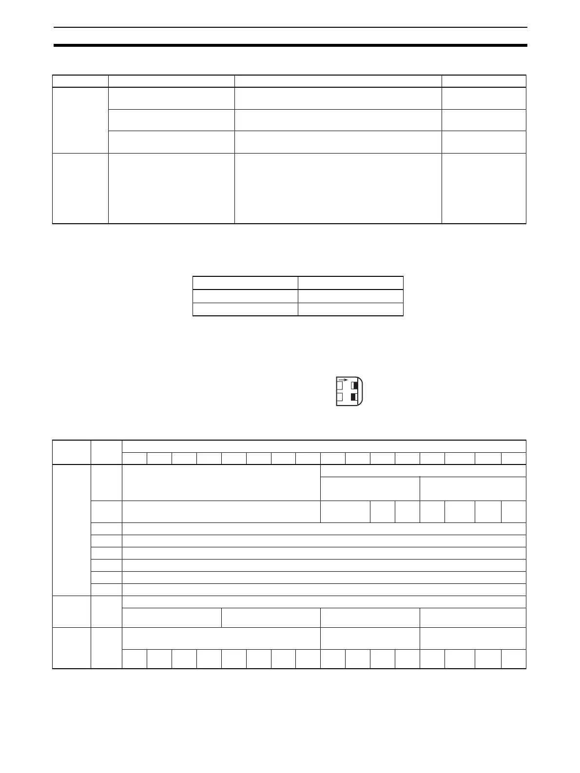
Allocation for Adjustment
Mode
For adjustment mode, set the operation mode switch on the front panel of the
Unit as shown in the following diagram, or set bits 00 to 07 in DM word m+18
to C1. When the Unit is set for adjustment mode, the ADJ indicator on the
front panel of the Unit will flash.
The allocation of CIO words and bits is shown in the following table.
Note 1. Use settings 1 to 4 for the CJ1W-AD041-V1.
2. With the CJ1W-AD041-V1, bits 04 to 07 in word n+9 (disconnection detec-
tion) are not used.
I/O Item Contents Page
Input Peak value hold function 0: Not used.
1: Peak value hold used.
110
Conversion value
Calculation result
16-bit binary data 105
Disconnection detection 0: No disconnection
1: Disconnection
111
Common Alarm Flags Bits 00 to 03: Disconnection detection
Bits 04 to 07: Disconnection detection
(not used for AD041-V1)
Bit 08-10: Not used
Bit 11: Mean value processing setting error
Bit 15: Operating in adjustment mode
(always 0 in normal mode)
102,121
103
Input signal range Voltage/current
1 to 5 V 0.3 V max.
4 to 20 mA 1.2 mA max.
O
N
12
MODE
ON
OFF
I/O Word Bits
1514131211109876543 2 10
Output
(CPU to
Unit)
n Not used. Inputs to be adjusted
2 (fixed)
1 to 8 (1 to 4) (See note
1.)
n + 1 Not used. Not used. Clr Set Up Down Gain Off-
set
n + 2 Not used.
n + 3 Not used.
n + 4 Not used.
n + 5 Not used.
n + 6 Not used.
n + 7 Not used.
Input
(Unit to
CPU)
n + 8 Conversion value at time of adjustment
16
3
16
2
16
1
16
0
n + 9 Alarm Flags Disconnection detec-
tion (See note 2.)
Not used.
Input
8
Input
7
Input
6
Input
5
Input
4
Input
3
Input
2
Input
1
 Loading...


